
Undershaft air door locking device for mining

A locking device and downwind technology, which is applied in the direction of mining equipment, mine/tunnel ventilation, mining equipment, etc., can solve the problems of long second guide rod, difficult manufacturing, fast wear of screw and nut, and increase the use of Long life, reduced maintenance cost, low maintenance requirements

Active Publication Date: 2020-04-10
LONGYAN LONGAN SAFETY TECH
View PDF6 Cites 2 Cited by
  • Summary
  • Abstract
  • Description
  • Claims
  • Application Information

AI Technical Summary

Problems solved by technology

But this way, first of all, in the power drive, it uses screw and screw nut, which will cause rapid wear of the screw and screw nut in the harsh underground environment, so the service life is not high
Moreover, to pull the air door, which is generally more than one meter high, into the ground, the length of the screw rod is relatively long, and the manufacturing is very difficult, that is, the actual manufacturing cost is extremely high, and the conventional process cannot achieve the corresponding precision at all.
In addition, the linkage method of the second guide rod will make the second guide rod very long, which obviously requires higher rigidity, strength and toughness of the second guide rod. Therefore, the above design is not practical
Although it solves the problem of roadway space occupation, it brings high cost in the current process environment
[0004] In this regard, the applicant proposes a locking device for mine dampers, which adopts chain linkage, and utilizes the characteristics of the chain being strong and insensitive to harsh environments, and combined with the design of the damper in the above-mentioned patent, the damper can occupy less space. Solve the problem of large roadway space and high cost

Method used


Image

  • Undershaft air door locking device for mining
  • Undershaft air door locking device for mining
  • Undershaft air door locking device for mining

Examples


Embodiment Construction

[0050] The following will clearly and completely describe the technical solutions in the embodiments of the present invention with reference to the drawings in the embodiments of the present invention.

[0051] In describing the present invention, it should be understood that the terms "upper", "lower", "front", "rear", "left", "right", "top", "bottom", "inner", " The orientation or positional relationship indicated by "outside", etc. is based on the orientation or positional relationship shown in the drawings, and is only for the convenience of describing the present invention and simplifying the description, rather than indicating or implying that the referred device or element must have a specific orientation, so as to Specific orientation configurations and operations, therefore, are not to be construed as limitations on the invention.

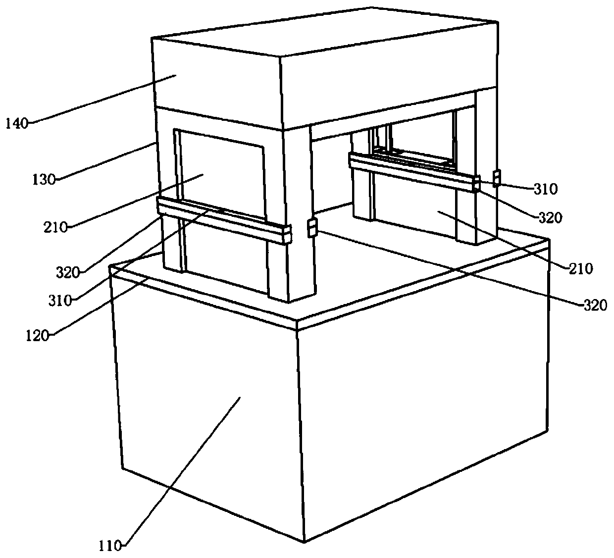
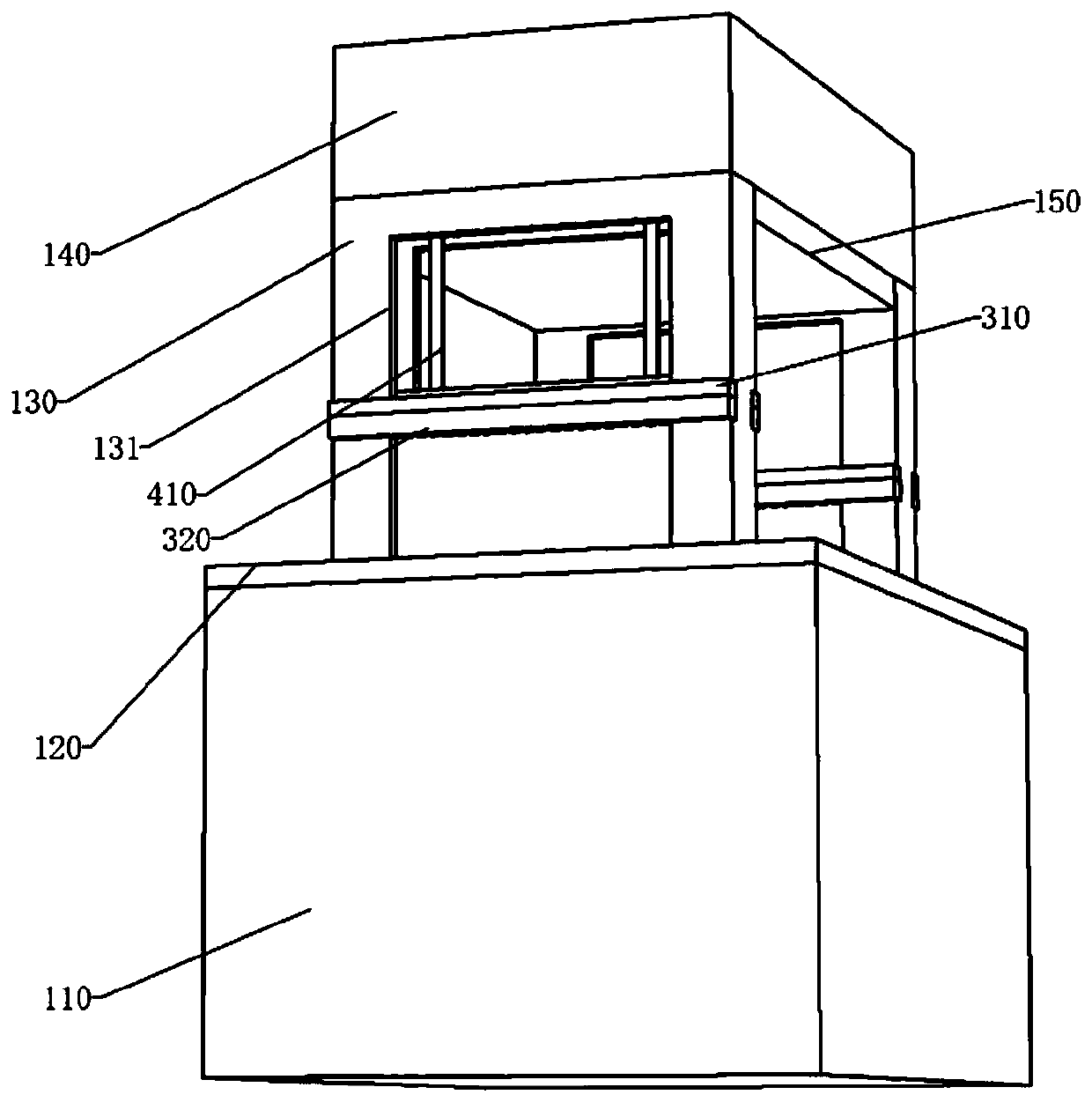
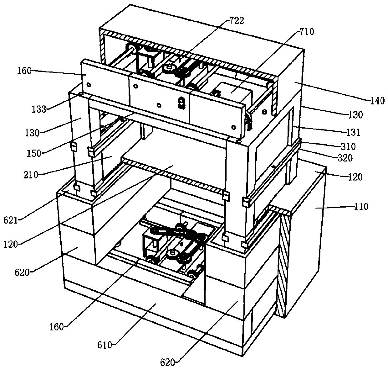
[0052] see Figure 1-Figure 19 , an underground damper locking device for mines, comprising a waterproof box 110, a top box 140, a botto...


PUM


Abstract

Disclosed is an undershaft air door locking device for mining. The undershaft air door locking device comprises a waterproof tank, a top tank, a bottom plate and at least two door frames, wherein thetop of the waterproof tank is open, the open end is sealed through the bottom plate, the bottom plate is flush with the ground of a roadway, the door frames are installed on the side walls of the roadway, the tops of the two door frames are connected and fixed through a top plate, and the top tank is fixed to the top plate; the bottoms of the door frames are fixed to the interiors of water collection inner hoods of water collection hoods, the door frames are respectively provided with door through grooves, door slide grooves and guide holes, and the interior of the top tank communicates with the interior of the waterproof tank through the guide holes; a door plank is slidably installed in each door slide groove, and the outer walls of the door planks and the inner walls of the door slide grooves are in sealable and slidable fitting; the top of one door plank and the corresponding chain block are fixedly assembled, each chain block and one end of a first chain are fixedly assembled, andthe first chain and the other door plank are fixedly assembled through the other chain block after the first chain is wound around the two first chains separately; and a connecting ring is arranged at the bottom of one door plank and fixedly connected with one end of a second chain, and the other end of the second chain and a connecting ring of the other door plank are fixedly assembled after theother end of the second chain penetrates out of a connecting sleeve.

Description

technical field [0001] The invention relates to ventilation equipment for mines, in particular to a locking device for an underground damper for mines. Background technique [0002] The damper in the mine is mainly used to cut off the wind flow. Generally, at least two dampers are required. When in use, choose one to open and the other to close. At present, most of the hydraulic interlocking mechanisms are used to open one of the two doors, but the hydraulic interlocking mechanism requires hydraulic pumps, hydraulic pipelines, etc., and hydraulic pipelines are vulnerable parts, which require regular maintenance and replacement, which will cause high costs for later maintenance. . In addition, the hydraulic interlock mechanism is generally installed behind the damper. Since the mine or air duct is not wide, this method may cause the damper to occupy too much mine space. Moreover, the downhole dust is relatively large, and the hydraulic method needs to add a large number of ...

Claims


Application Information

Patent Timeline
IPC IPC(8): E21F1/12E21F1/10E21F17/00
CPCE21F1/10E21F1/12E21F17/00
Inventor 郭玉森仲涛薛冰峰刘谦王世潭林世豪张文武杨元杰
Owner LONGYAN LONGAN SAFETY TECH
Learn More