Eureka AIR delivers breakthrough ideas for toughest innovation challenges, trusted by R&D personnel around the world.

Construction method for detecting and treating karst cave through tunnel advance large pipe shed

A technology of advanced large pipe shed and construction method, which is applied in the construction field of tunnel advanced support measures, can solve problems such as increased engineering costs, casualties, and slowed down construction speed, so as to reduce the amount of reinforcement works, improve detection accuracy, reduce collapse effect

Active Publication Date: 2020-04-10
RES INST OF HIGHWAY MINIST OF TRANSPORT +1
View PDF5 Cites 2 Cited by
  • Summary
  • Abstract
  • Description
  • Claims
  • Application Information

AI Technical Summary

Problems solved by technology

However, in actual engineering applications, the results of advanced geological prediction cannot accurately provide important information such as the type, scale, and spatial location of the cave, and it is difficult to determine the construction mileage and area of ​​the advanced large-scale pipe shed. Tube sheds, significantly slowing down construction and increasing engineering costs
[0003] Since there is no more reliable method, the current construction unit only conducts advanced large-scale pipe shed construction when the karst cave is exposed on the face of the tunnel and combined with the results of the advanced geological forecast to determine that the karst cave is large and the stability of the filling is poor. Failure to ensure sufficient anti-outburst rock plate thickness often leads to large-scale landslides or filling surge disasters in large anhydrous karst caves exposed or not exposed on the tunnel face during tunnel construction, and the treatment of large anhydrous filled karst caves has little effect
[0004] The existing drilling method to detect advanced geology is to use a drilling rig to drill 4 to 6 holes radially in four directions on the tunnel face, which is suitable for water-rich karst tunnels and is mainly used to detect the occurrence of water in the strata ahead and obtain information It is mainly the water pressure and water volume of the groundwater, and the parameters such as the scale and specific location of the cave in front cannot be obtained. For example, the drilling method disclosed in the patent No. 201710046172.6 and the patent name "Tunnel Karst Water Detection and Treatment Method" is a solution. The existing tunnel karst water is easy to hinder the construction and cause casualties, and it is not suitable for detecting and treating large anhydrous filled caves or caves filled with viscous materials such as silt

Method used


Image

  • Construction method for detecting and treating karst cave through tunnel advance large pipe shed
  • Construction method for detecting and treating karst cave through tunnel advance large pipe shed
  • Construction method for detecting and treating karst cave through tunnel advance large pipe shed

Examples


Embodiment 1

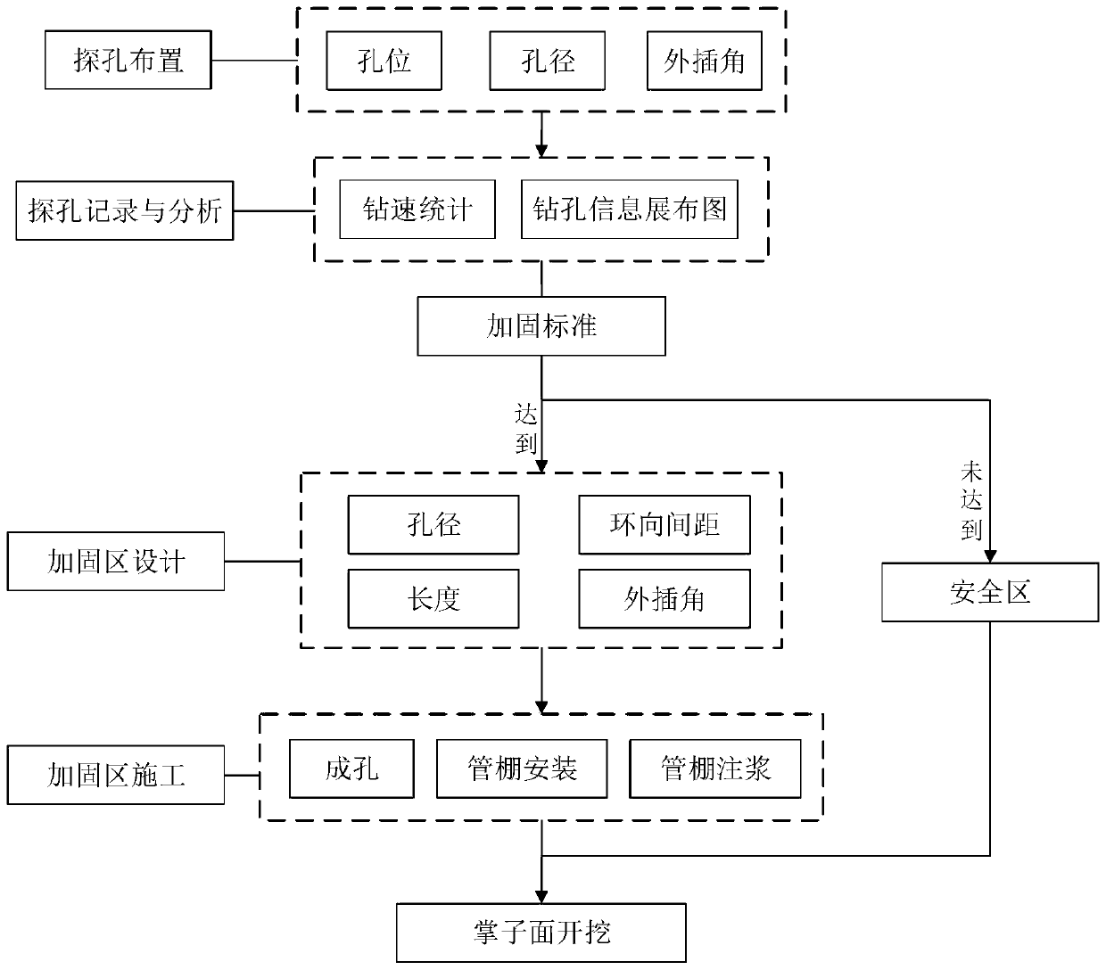
[0035] Embodiment one, such as figure 1 As shown, a construction method for detecting and treating karst caves in advance of large pipe sheds in tunnels, including the following steps:

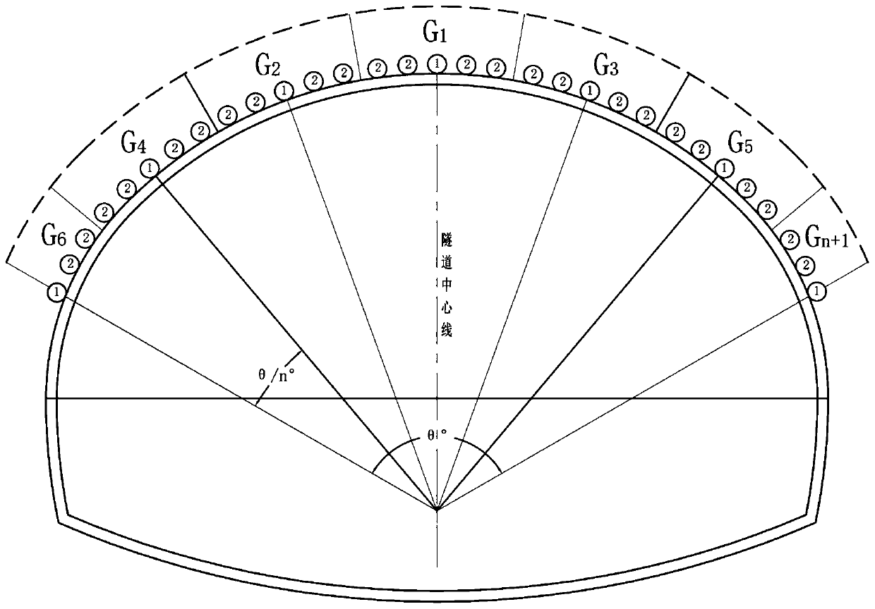
[0036] (1) Combined with the results of geological exploration, pipe shed holes are drilled on the tunnel face. The pipe shed holes drilled include the detection holes drilled in the early stage and the reinforcement holes drilled in the later stage. For detection, the reinforcement holes are arranged on both sides of the detection hole for reinforcement, and the detection holes and reinforcement holes are arranged in the tunnel arch according to a predetermined arrangement.

[0037] (2) The detection hole and the reinforcement hole are all drilled forward along the excavation direction of the tunnel, and during the drilling process of the detection hole, the drilling speed of the drilling hole is recorded and the drilling information distribution map is drawn;

[0038] (3) Determine the scop...

Embodiment 2

[0052] Embodiment 2 is a three-lane and three-center-circle tunnel, and the outer contour span of the tunnel is about 17.0m. The implementation steps of the technical solution include:

[0053] 1. Arrange 7 detection holes at 20° intervals in the 120° range of the arch. The detection hole diameter is 80mm, and the circumferential spacing of the detection holes is about 3.2m. Adjacent detection holes can find caves with a circumferential width greater than 3.2m. The 1.6m on both sides of each detection hole is used for partitioning, and the θ° range of the arch is divided into seven partitions: G1, G2...G7.

[0054] 2. The length of the detection hole is 30m, and the extrapolation angle is a 1 10-12° to ensure that caves with a height greater than 5m can be detected at the tail end.

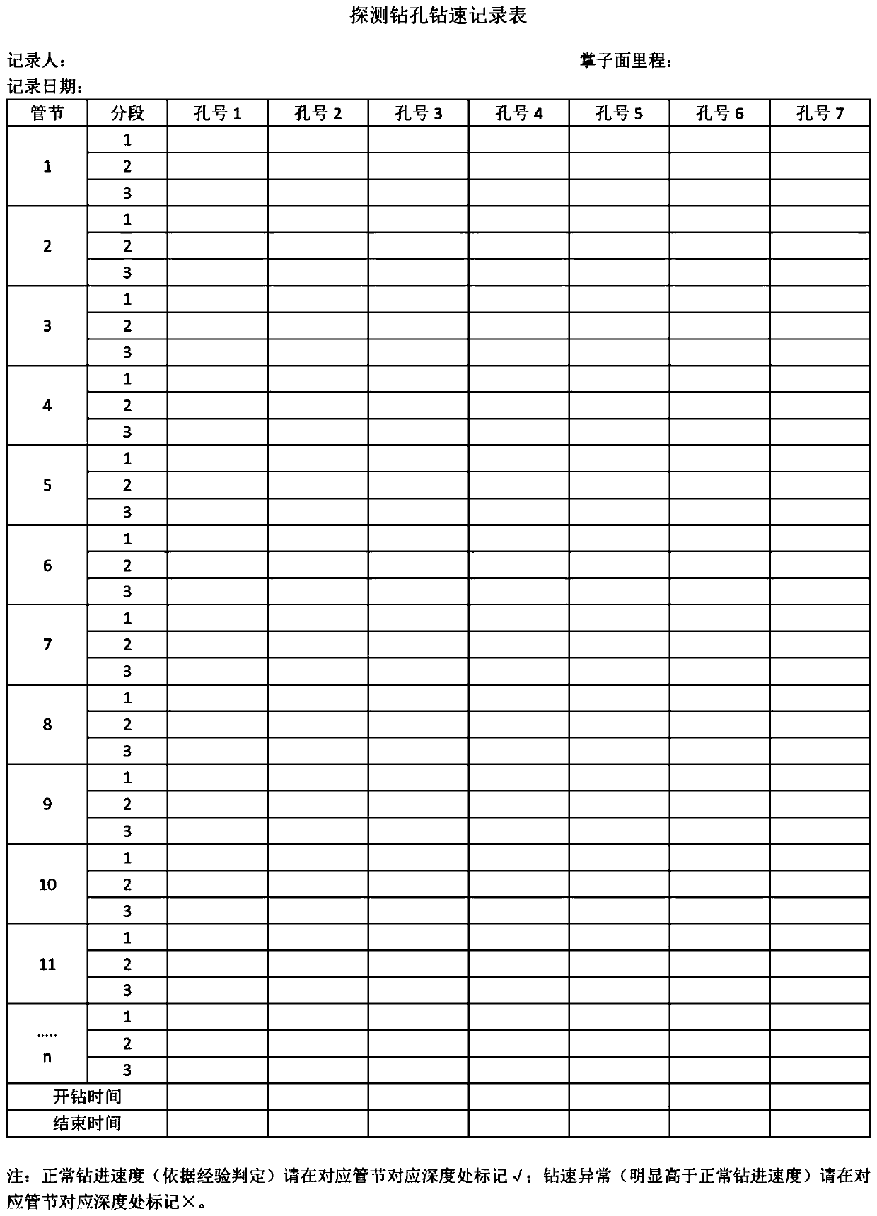
[0055] 3. Use the attached image 3 In the table, record the drilling speed during the drilling process of each detection hole, and use the attached Figure 4 The distribution map of the explor...


PUM


Abstract

The invention relates to the technical field of tunnel advance support measure construction, in particular to a construction method for detecting and treating a karst cave through a tunnel advance large pipe shed. The method includes the following steps that (1) pipe shed holes are formed in a tunnel, wherein the pipe shed holes include detection holes and reinforcement holes, and the detection holes and the reinforcement holes are formed in the arch part of the tunnel according to a set arrangement mode; and (2) the detection holes and the reinforcement holes are drilled in the arch part of the tunnel in the tunnel excavation direction, and in the detection hole drilling process, the drilling rate of the drilled holes is recorded and a drilled hole information distribution map is drawn. Compared with the prior art, the method has the advantages that in the method, based on the geological features and technical status of the large no-water filled karst cave in the front of the tunnel,the functional localization of the advance large pipe shed to localize the karst cave firstly and then reinforce the karst cave is clarified, and the pipe shed holes are divided into two types, namely, the detection holes and the reinforcement holes.

Description

technical field [0001] The invention relates to the technical field of construction of tunnel advance support measures, in particular to a construction method for detecting and treating karst caves in advance of tunnel sheds. Background technique [0002] Tunnels in karst-developed strata reveal that large anhydrous filled karst caves are prone to geological disasters such as cave collapse, filling surge, and surface subsidence, causing great losses to life and property. At present, for this kind of geological disaster, the common method of tunnel construction is to use the advanced geological forecast results of the long-distance and short-distance comprehensive geophysical prospecting method as the basis for treatment, and adopt the advanced large-pipe shed measure for advanced treatment. However, in actual engineering applications, the results of advanced geological prediction cannot accurately provide important information such as the type, scale, and spatial location of...

Claims


Application Information

Patent Timeline
IPC IPC(8): E21D11/14E21D11/10E21B45/00E21B47/00
CPCE21B45/00E21B47/00E21D11/10E21D11/14
Inventor 万飞李磊王波付重滔孔德抗
Owner RES INST OF HIGHWAY MINIST OF TRANSPORT
Why Eureka
Eureka Blog
Learn More