
A hydraulically assisted splitting equipment for rock crushing

A hydraulic and rock technology, which is applied in the field of hydraulic assisted splitting equipment, can solve the problems of unfavorable crushing and high rock integrity, and achieve the effect of reducing resistance and easy decomposition and cracking

Active Publication Date: 2021-05-18
佛山市华磊华扬机械有限公司
View PDF9 Cites 0 Cited by
  • Summary
  • Abstract
  • Description
  • Claims
  • Application Information

AI Technical Summary

Problems solved by technology

[0004] Aiming at the deficiencies in the prior art, the purpose of the present invention is to provide a hydraulically assisted splitting equipment for rock crushing, so as to solve the problem of digging a small hole in the rock surface when the prior art is crushing. The rocks along the edge are broken, and there is no further impact on the broken rocks, so that the integrity of the broken rocks is still high, which is not conducive to further crushing.

Method used


Image

  • A hydraulically assisted splitting equipment for rock crushing
  • A hydraulically assisted splitting equipment for rock crushing
  • A hydraulically assisted splitting equipment for rock crushing

Examples


Embodiment 1

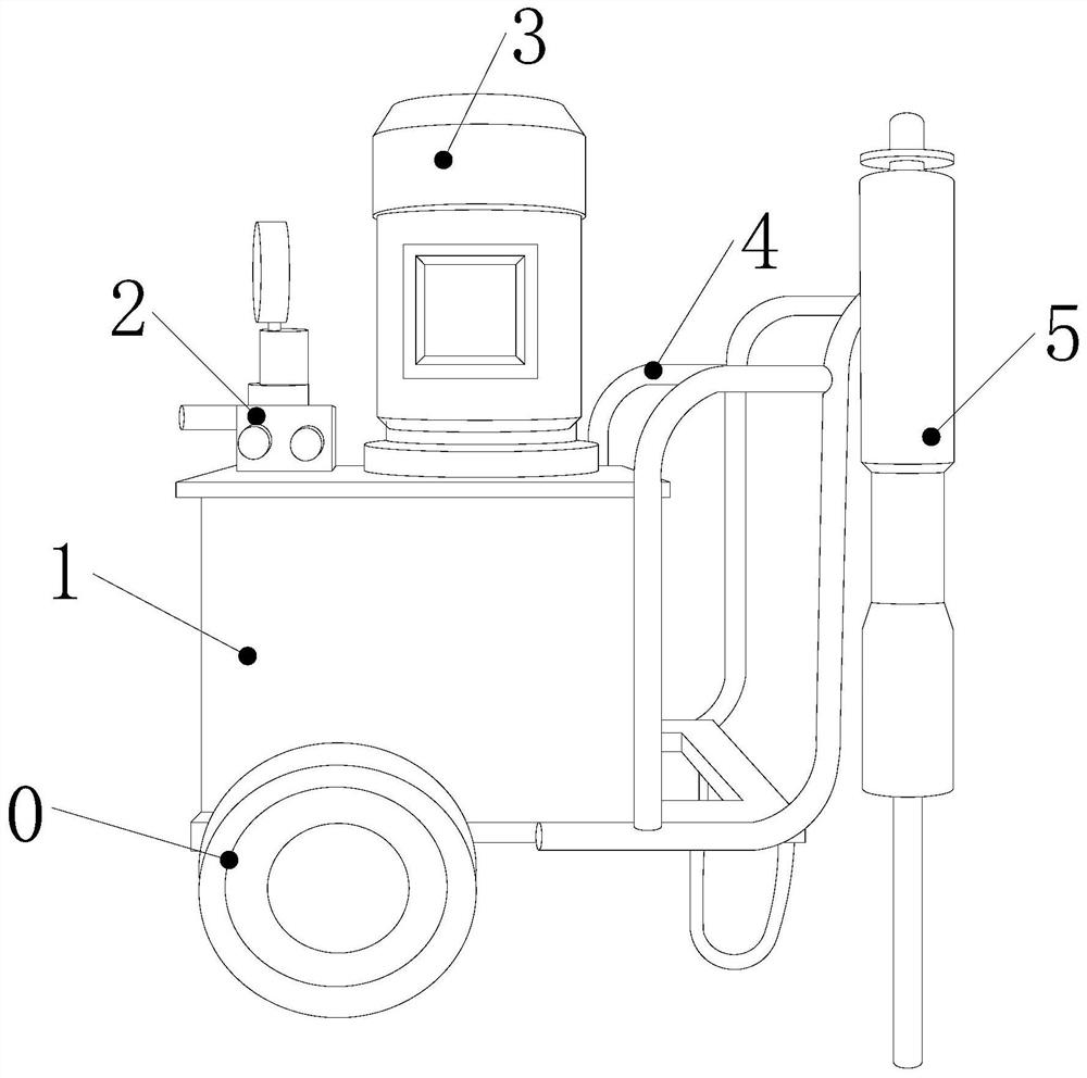
[0025] see Figure 1-Figure 5 , the present invention provides a hydraulic auxiliary splitting equipment for rock crushing: its structure includes a walking frame 0, a conversion cabinet 1, an output valve 2, a hydraulic pump 3, a pushing frame 4, and a hydraulic crushing device 5, and the walking frame 0 Locked below the conversion case 1 by rivets, the hydraulic pump 3 is vertically threaded on the top of the conversion case 1, the output valve 2 is nailed to the left side of the hydraulic pump 3 and connected with the conversion case 1, so The pushing frame 4 is welded on the right side of the conversion case 1, the hydraulic breaking device 5 is fastened in front of the pushing frame 4 and screwed together with the output valve 2, and the hydraulic breaking device 5 is composed of an infusion head 50 , a conduction cylinder 51, a connecting arm 52, a suction structure 53, and a multi-ring breaking rod 54. The infusion head 50 is screwed together with the output valve 2, an...

Embodiment 2

[0028] On the basis of Example 1, please refer to Image 6, the anti-suction structure 53 is composed of a pressed channel 530, an anti-suction pile 531, a U-shaped transition channel 532, a dust cleaning belt 533, a barrier net 534, and a pressing strip 535. In the middle section of the interior, the anti-suction pile 531 is electric welded on the left side of the connecting arm 52, and the U-shaped transition channel 532 is provided with more than two upper and lower ends of the anti-suction pile 531 through buckles. The dust belt 533 is mechanically connected to the inside of the U-shaped transfer channel 532, the barrier net 534 is slidably connected to the inside of the U-shaped transfer channel 532, and the pressing strip 535 is movably connected to the upper and lower ends of the pressed channel 530 and is connected to all The U-shaped transition 532 fits together flexibly. When the rock is broken, some dust will appear due to internal cracking and edge friction. At thi...


PUM


Abstract

The invention discloses a hydraulic auxiliary splitting equipment for rock crushing. The structure includes a walking frame, a conversion box, an output valve, a hydraulic pump, a pushing frame, and a hydraulic breaking device. The walking frame is locked under the switching box by rivets. , the hydraulic pump is vertically threaded on the top of the conversion case, not only can the hexagonal drilling and cutting blades and wedge rings continuously separate the inside of the hole when drilling the rock surface, amplifying the driving force of the hydraulic equipment, and Through the segmentation effect of alloy sheet, cutting column, and wave sheet, it can have a strong segmentation effect on the rocks at both ends. When segmenting the rocks on the straight-line distance, it can play a role in frictional segmentation of the rocks on the side. , so that the integrity of the rocks in other areas is damaged, it can be more easily decomposed and cracked, and the resistance encountered when the subsequent hydraulic equipment is advanced is reduced.

Description

technical field [0001] The invention relates to a hydraulic device, in particular to a hydraulic auxiliary splitting device for rock crushing. Background technique [0002] Hydraulic equipment is based on liquid as the medium and transmits kinetic energy through the kinetic energy of the liquid. When crushing rocks, the traditional blasting technology is eliminated through hydraulic equipment, making the crushing of rocks more environmentally friendly. It relies on converting the kinetic energy of the liquid into the energy of cutting and drilling, and cracking the rock into multiple pieces. The current technology is not comprehensive and has the following disadvantages: [0003] In the prior art, a small hole needs to be dug on the surface of the rock during crushing. After deep penetration, only the rock along the broken edge is often crushed, without further impact on the crushed rock, so that the integrity of the crushed rock remains intact. Higher, not conducive to fur...

Claims


Application Information

Patent Timeline
Patent Type & Authority Patents(China)
IPC IPC(8): E21C37/12
CPCE21C37/12
Inventor 李志强
Owner 佛山市华磊华扬机械有限公司
Learn More