Wire winding structure and clothes hanger hand cranking device

A wire winding and wire reel technology, which is applied in the field of clothes drying machines, can solve the problems of overlapping each other, the shaking of clothes drying racks, the bending of steel wire ropes, etc., so as to achieve the effect of prolonging life and easy and orderly winding.

Pending Publication Date: 2020-04-10
九牧智能厨卫(安徽)有限公司
View PDF2 Cites 0 Cited by
  • Summary
  • Abstract
  • Description
  • Claims
  • Application Information

AI Technical Summary

Problems solved by technology

[0002] At present, in various types of hand cranks on the market, the steel wire rope is mostly coiled directly on the reel, and the connection between the steel wire rope and the reel is very abrupt, which will easily lead to bending of the steel wire rope and affect the life of the steel wire rope. Both of them only have the function of winding and unwinding in one direction (such as clockwise winding and anticlockwise winding). If the user does not take up the thread in the predetermined direction, such as counterclockwise, when the winding wheel in the hand crank When the steel wire rope is exhausted, the steel wire rope will be wound on the winding wheel in the opposite direction when the winding wheel continues to rotate in the same direction. At this time, if you continue to take up the thread counterclockwise, it will cause the rolled-up steel wire rope to slip sideways, causing the wire rope to jump, which will cause the clothes hanger to vibrate or even fall off, causing a safety accident; and the wire rope jumps or is disorderly The entanglement will also cause the user to operate the hand crank unsmoothly, which will affect the user experience

Method used


Image

  • Wire winding structure and clothes hanger hand cranking device
  • Wire winding structure and clothes hanger hand cranking device
  • Wire winding structure and clothes hanger hand cranking device

Examples


Embodiment Construction

[0033] The technical solutions in the embodiments of the present invention will be clearly and completely described below with reference to the accompanying drawings in the embodiments of the present invention. Obviously, the described embodiments are preferred embodiments of the present invention and should not be construed to exclude other embodiments. Based on the embodiments of the present invention, all other embodiments obtained by those of ordinary skill in the art without creative efforts fall within the protection scope of the present invention.

[0034] In the claims, description and the above drawings of the present invention, unless otherwise clearly defined, the terms "first", "second" or "third" are used to distinguish different objects, rather than used for Describe a specific order.

[0035]In the claims, description and the above drawings of the present invention, unless otherwise expressly defined, the terms "center", "horizontal", "longitudinal", "horizonta...


PUM


Abstract

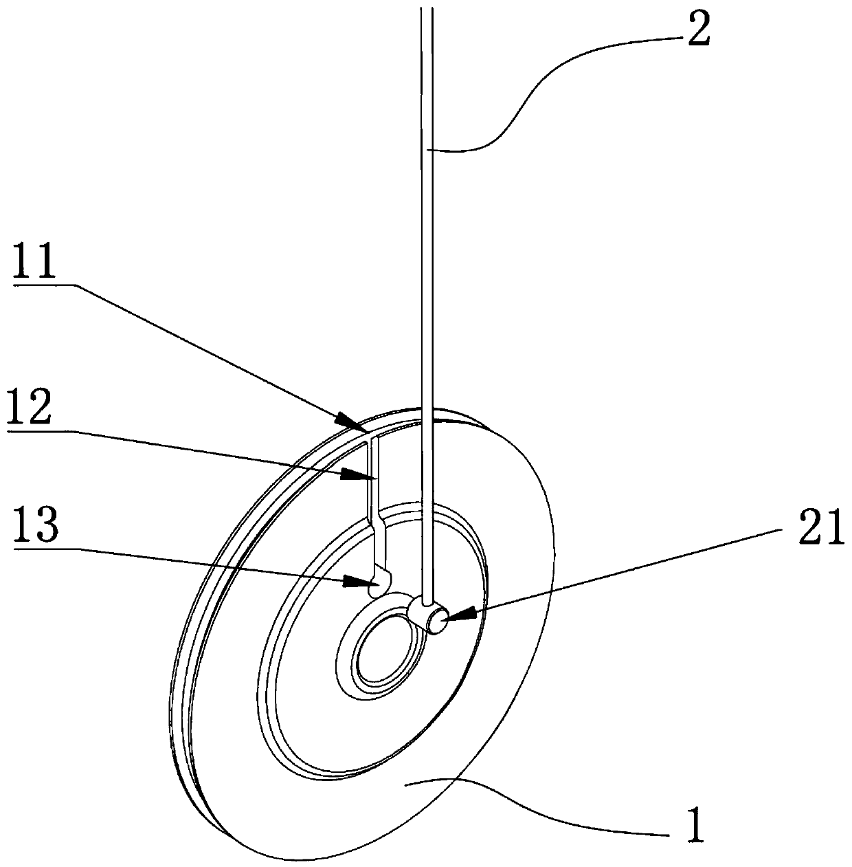
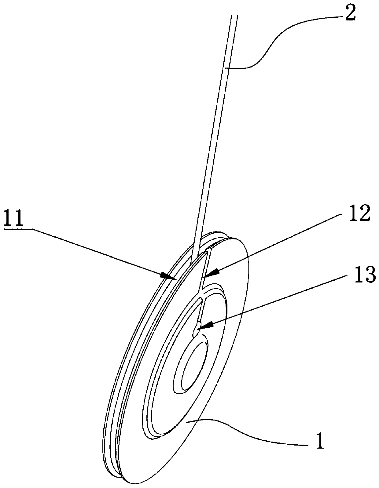
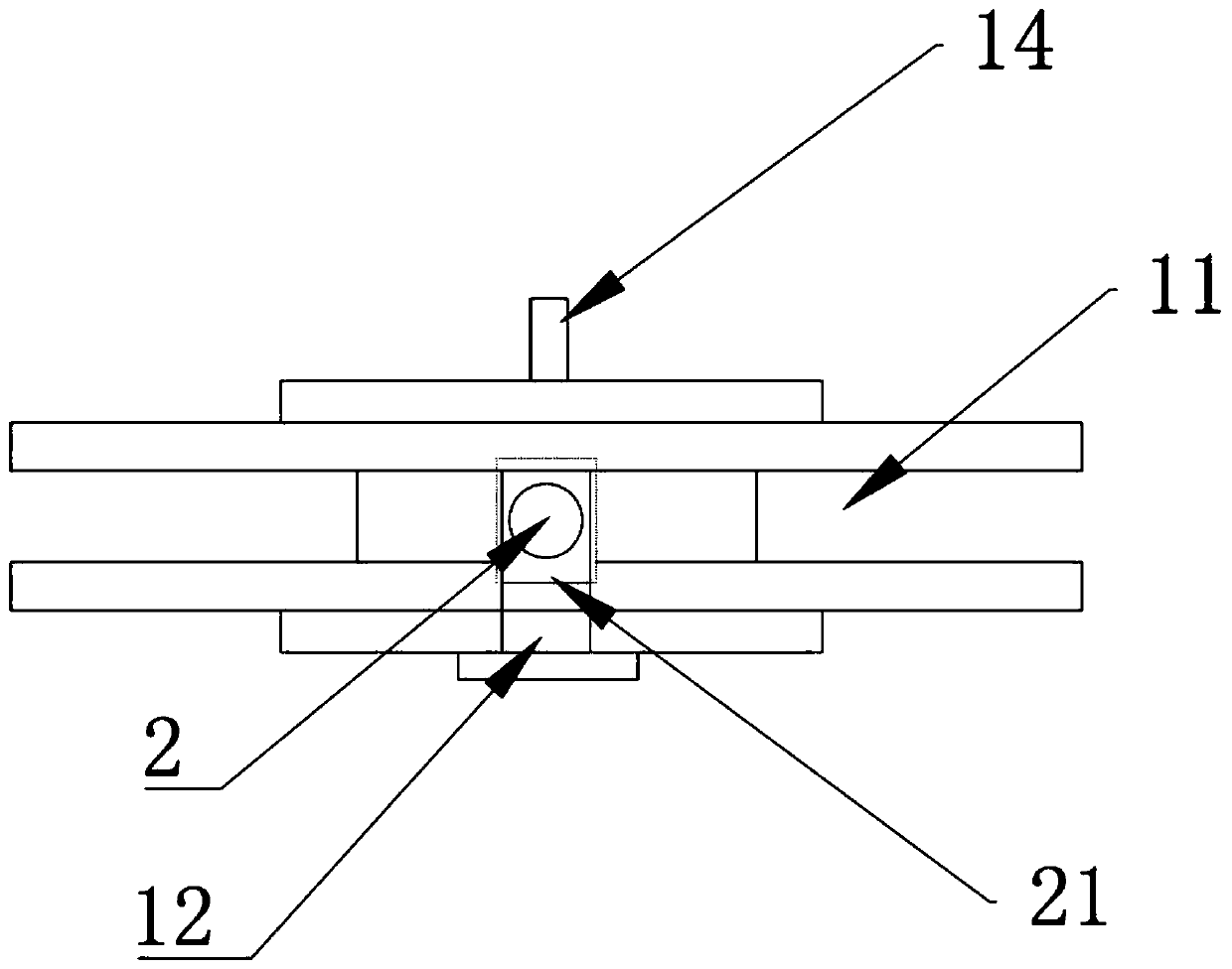
The invention discloses a wire winding structure and a clothes hanger hand cranking device. The wire winding structure comprises a wire winding wheel and a steel wire rope, wherein an accommodating groove with an outward opening is formed in the peripheral wall of the wire winding wheel, and a guide groove communicating with the accommodating groove is formed in the side wall of the wire winding wheel; the steel wire rope enters the accommodating groove in the depth direction of the guide groove, and one end of the steel wire rope is rotationally connected with the wire winding wheel; a limiting structure is further arranged on the wire winding wheel and is used for limiting the steel wire rope from being disengaged from the wire winding wheel from the guide groove; and when the wire winding wheel rotates, the wire winding wheel is released or rolled. According to the winding structure and the clothes hanger hand cranking device, the service life of the steel wire rope can be prolonged, winding of the steel wire rope is smoother and more natural, and the use experience of a user is good.

Description

technical field [0001] The invention relates to the field of clothes drying machines, in particular to a wire winding structure and a hand crank for clothes drying racks. Background technique [0002] For various types of hand cranks on the market, the wire rope is mostly coiled directly on the reel, and the connection between the wire rope and the reel is very abrupt, which easily causes the wire rope to bend and affects the life of the wire rope. All of them only have the function of taking up and paying off the wire in one direction (for example, it can only take up the wire clockwise and pay off the wire counterclockwise). When the wire rope is exhausted, the wire rope will be reversely wound on the reel while the reel continues to rotate in the same direction. Overlap, if you continue to take up the wire counterclockwise at this time, the coiled wire rope will slip sideways, causing the wire rope to jump, which will cause the drying rack to shake or even fall off, caus...

Claims


Application Information

Patent Timeline
IPC IPC(8): D06F57/12
CPCD06F57/125
Inventor 林孝发林孝山季辉沈国俊刘晓森
Owner 九牧智能厨卫(安徽)有限公司
Why Eureka
Try Eureka