
Textile machine yarn guide device

A technology of mechanical guidance and textile, which can be used in transportation and packaging, transportation of filamentous materials, thin material processing, etc., and can solve problems such as poor effect.

Inactive Publication Date: 2020-04-10
唐红英
View PDF4 Cites 10 Cited by
  • Summary
  • Abstract
  • Description
  • Claims
  • Application Information

AI Technical Summary

Problems solved by technology

[0004] Chinese patent (notification number: CN206814130U) discloses a yarn guide device for textile machinery, including a dust-proof board, a rotating shaft and a support rod. The inner surface of the dust-proof board is welded with a support rod, and the upper end of the hole, the center of the socket is plugged with a rotating shaft, the outer wall of the rotating shaft is fixedly connected with a winding roller, the outer wall of the winding roller is wrapped with textile yarn, and the winding roller is connected with the active rotating shaft through the textile yarn. The center of the driving roller is connected with a rotating shaft, the two ends of the rotating shaft are sleeved with bearings, and one side of the rotating shaft is welded with a driven gear, and the other end of the toothed belt is sleeved with the driving gear. Then, the driving gear is welded on the outer wall of the power output shaft, and one side of the power output shaft is fixedly connected with the motor. The yarn guiding device of this textile machine is equipped with a dustproof board outside the yarn guiding device. In the process, it can ensure that the textile yarn will not be polluted by impurities in the air, and ensure the smooth operation of the subsequent process. However, the device is too simple, resulting in poor yarn guiding effect, so it needs to be improved.

Method used

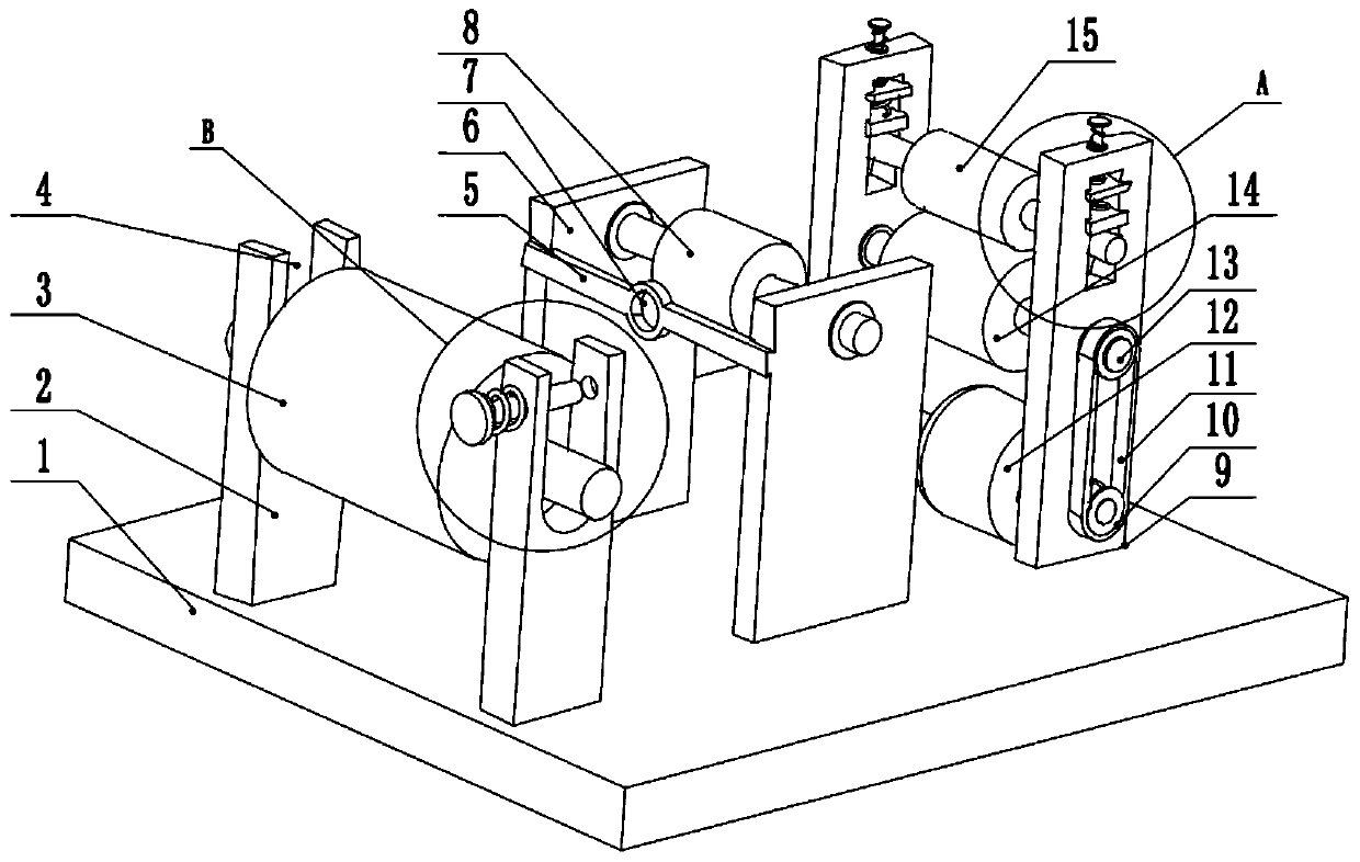
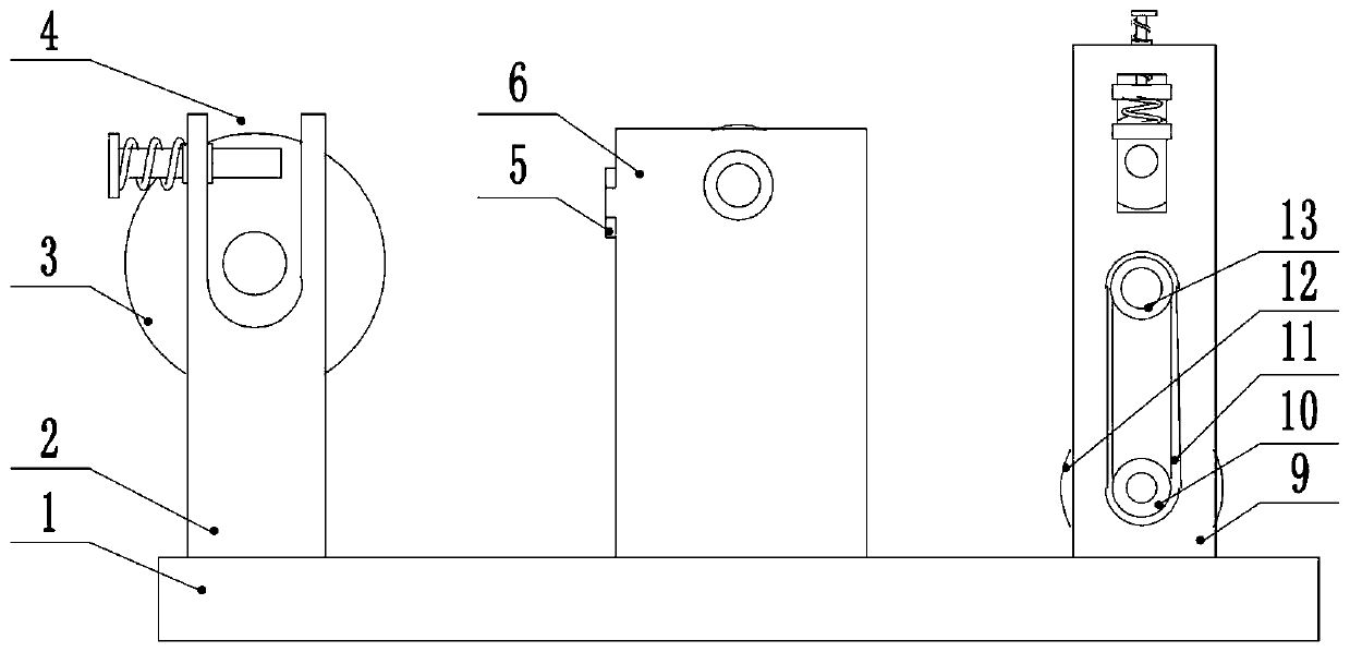
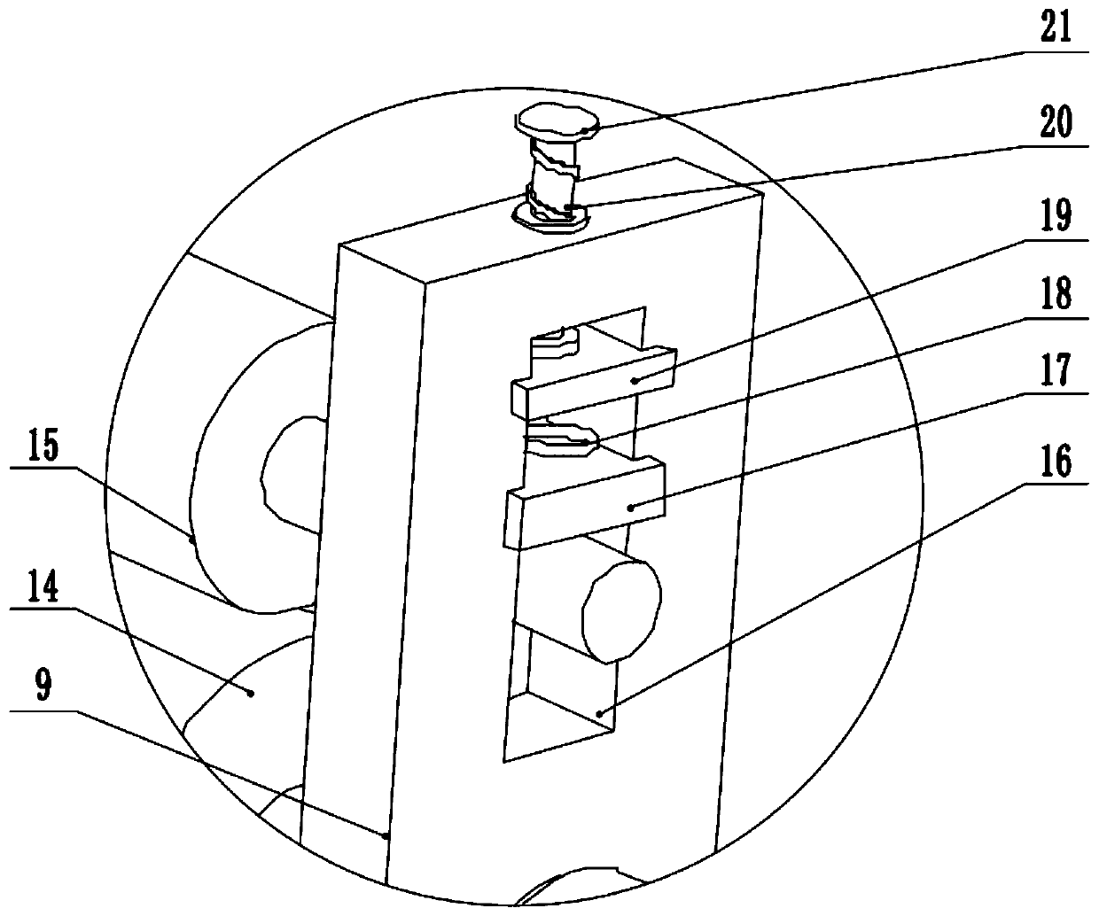

Image

  • Textile machine yarn guide device
  • Textile machine yarn guide device
  • Textile machine yarn guide device

Examples


Embodiment 1

[0027] see Figure 1-3 , a yarn guide device for textile machinery, comprising a bottom plate 1, a first fixing seat 2 is provided on the left side of the upper surface of the bottom plate 1, a placement groove 4 is arranged on the upper part of the first fixing seat 2, and a winding roller 3 is arranged inside the placement groove 4 , the left side of the placement groove 4 is slidingly connected to the limit rod 24, the left end of the limit rod 24 is provided with a limit plate 22, and an extension spring 23 is arranged between the limit plate 22 and the left side of the first fixed seat 2, and the extension spring 23 Sleeved on the outside of the limit rod 24, the right side of the placement groove 4 is provided with a limit hole 25 that cooperates with the limit rod 24. By setting the limit hole 25, when the limit rod 24 slides to the rightmost end, the limit The rightmost end of the rod 24 is just inserted in the limit hole 25. At this time, the position of the limit rod...

Embodiment 2

[0030] see Figure 1-3 , a yarn guide device for textile machinery, comprising a bottom plate 1, a first fixing seat 2 is provided on the left side of the upper surface of the bottom plate 1, a placement groove 4 is arranged on the upper part of the first fixing seat 2, and a winding roller 3 is arranged inside the placement groove 4 , the left side of the placement groove 4 is slidingly connected to the limit rod 24, the left end of the limit rod 24 is provided with a limit plate 22, and an extension spring 23 is arranged between the limit plate 22 and the left side of the first fixed seat 2, and the extension spring 23 Sleeved on the outside of the limit rod 24, the right side of the placement groove 4 is provided with a limit hole 25 that cooperates with the limit rod 24. The middle part of the upper surface of the bottom plate 1 is provided with a second fixed seat 6, and the second fixed seat 6 The upper part of the rotating connection tension roller 8.

[0031] The uppe...


PUM


Abstract

The invention relates to the technical field of textiles and discloses a textile machine yarn guide device. The textile machine yarn guide device comprises a bottom plate, a first fixing seat is arranged on the left side of the upper surface of the bottom plate, a containing groove is formed in the upper portion of the first fixing seat, a winding roller is arranged in the containing groove, a second fixing seat is arranged in the middle of the upper surface of the bottom plate, a tension roller is connected with the upper portion of the second fixing seat in a rotating mode, a third fixing seat is arranged on the right side of the upper surface of the bottom plate, a supporting roller is connected with the middle of the third fixing seat in a rotating mode, a sliding groove is formed in the upper portion of the third fixing seat, a pressing roller is connected with the lower portion of the sliding groove in a sliding mode, a pressing block is connected with the middle of the sliding groove in a sliding mode, and the upper portion of the pressing block is connected with the lower end of a spring. According to the textile machine yarn guide device, the pressing roller capable of sliding vertically is arranged on the right side of the device, and thus the free end of yarn is clamped tightly through the pressing roller and the supporting roller; and besides, the deformation amountof the spring changes along with rotation of a lead screw, and thus the clamping force of the pressing roller to the yarn can be adjusted freely.

Description

technical field [0001] The invention relates to the technical field of textiles, in particular to a yarn guiding device for a textile machine. Background technique [0002] Ancient Chinese textile and printing and dyeing technology has a very long history. As early as in the primitive society, in order to adapt to climate change, the ancients knew how to obtain local materials, use natural resources as raw materials for textile and printing and dyeing, and manufacture simple textile tools. Today, our daily clothing, some daily necessities and artworks are all products of weaving and printing and dyeing technology. [0003] The textile yarn guide device is a device used for guiding the spinning bobbin in the work of the textile machine, and it is one of the indispensable accessory devices in the textile work. The existing textile yarn guide seat includes a base and a yarn guide needle , the inside of the base is provided with a placement cavity, and a positioning plate is ar...

Claims


Application Information

Patent Timeline
IPC IPC(8): B65H57/14B65H59/10B65H57/06B65H49/30
CPCB65H49/30B65H57/06B65H57/14B65H59/10B65H2701/31
Inventor 唐红英
Owner 唐红英
Learn More