Non-return power cable take-up and pay-off device

A power cable and retractable device technology, which is applied in the field of power cables, can solve the problems that the cable ends cannot be fixed and unwound, and achieve the effects of simple structure, strong practicability, and easy operation

Pending Publication Date: 2020-04-10
何伟
View PDF14 Cites 2 Cited by
  • Summary
  • Abstract
  • Description
  • Claims
  • Application Information

AI Technical Summary

Problems solved by technology

[0004] The purpose of the present invention is to provide a non-returnable power cable retracting device to solve the problems that the rear end of the cable cannot be fixed and the cable is long

Method used


Image

  • Non-return power cable take-up and pay-off device
  • Non-return power cable take-up and pay-off device
  • Non-return power cable take-up and pay-off device

Examples


Embodiment 1

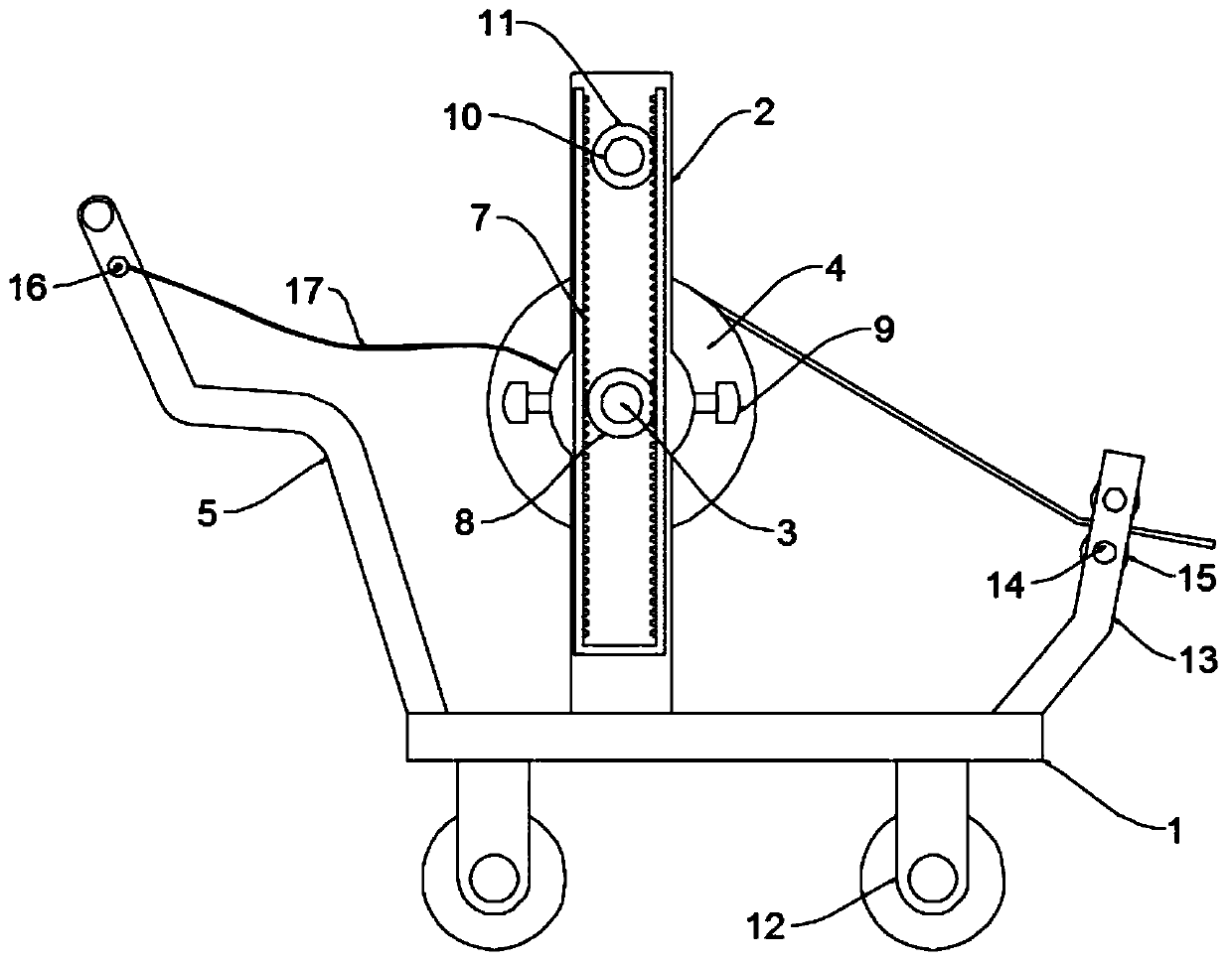
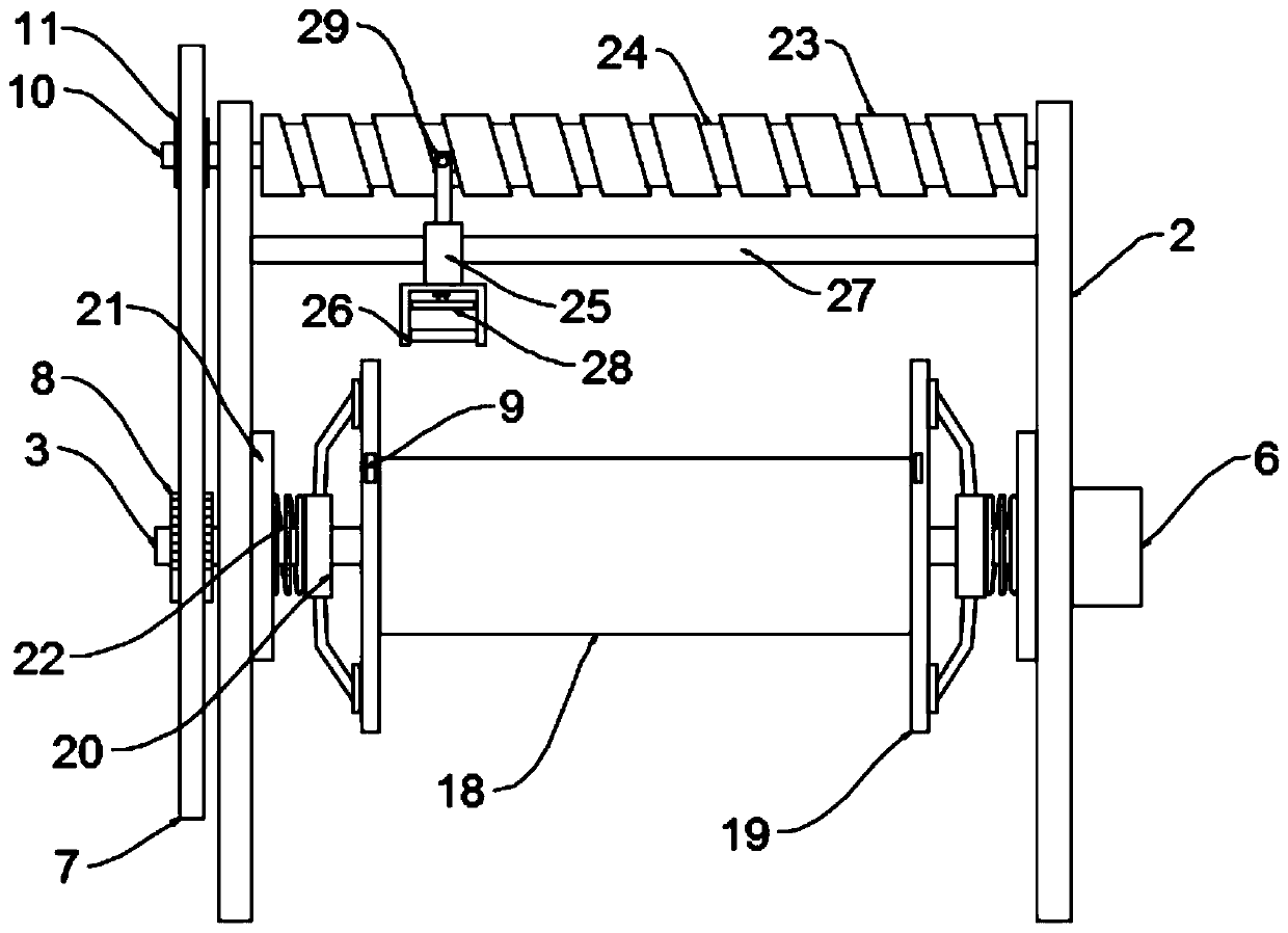
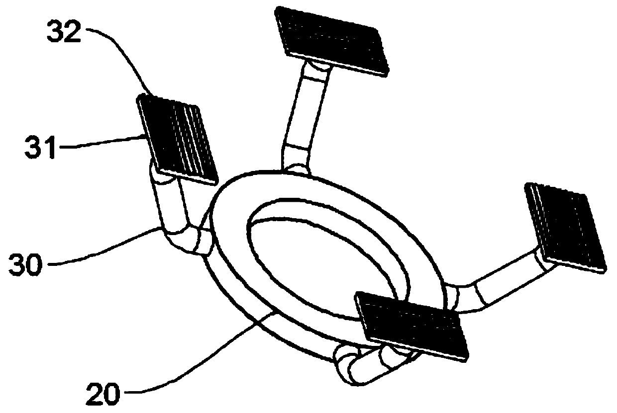
[0022] see Figure 1~3 , in an embodiment of the present invention, a non-returnable power cable retracting device includes a frame body 1 and a roll member 4, the bottom of the frame body 1 is provided with a moving roller 12, and the frame body 1 is provided with The vertical rod frame 2 is installed and the retractable rod shaft 3 is installed on the vertical rod frame 2, and the roll part 4 is fixed on the retractable rod shaft 3, and one end of the retractable rod shaft 3 is arranged on the vertical rod The retractable motor 6 on the frame 2 is connected, and the rolling member 4 is composed of a winding roller 18 and side baffles 19 fixed at the two ends of the winding roller 18, and the two ends of the retracting rod shaft 3 are A limiting mechanism is provided, and the limiting mechanism includes an installation iron ring 20 rotatably installed on the retractable rod shaft 3 and an electromagnetic block 21 fixed on the installation pole frame 2. The outer wall of the i...

Embodiment 2

[0028] The difference between the embodiment of the present invention and embodiment 1 is that: the end of the frame body 1 away from the push rod frame 5 is provided with a side rod frame 13 and two guide rods 14 are arranged on the side rod frame 13, each guide rod The guide pulley 15 that slides thereon is all provided with on the bar 14, forms a slit between two guide pulleys 15, and this slit is used for the cable to pass through so as to avoid that the cable contacts the end of the frame body 1 when rewinding. Scratch the skin.


PUM


Abstract

The invention discloses a non-return power cable take-up and pay-off device. The device comprises a rack body and a winding roller part, a moving roller is arranged at the bottom of the rack body; a mounting vertical rod frame is arranged on the rack body, and a rod winding and unwinding shaft is mounted on the mounting vertical rod frame. The winding roller part is fixed on the winding and unwinding shaft; one end of the winding and unwinding shaft is connected with a winding and unwinding motor arranged on the mounting vertical rod frame; the winding roller part is composed of a winding roller and side baffles fixed to the two ends of the winding roller. Limiting mechanisms are arranged at the two end parts of the winding and unwinding shaft; each limiting mechanism comprises a mountingiron ring rotationally mounted on the winding and unwinding shaft and an electromagnetic block fixed on the mounting vertical rod frame; a plurality of annularly-distributed supporting rods are arranged on the outer wall of the mounting iron ring, friction plates with the front faces facing the side baffles are arranged at the ends of the supporting rods, a plurality of protruding edges are arranged on the friction plates, and the mounting iron ring is connected with the electromagnetic block through a reset spring. The cable take-up and pay-off device is simple in structure, simple and convenient to operate and high in practicability, and the situation that the end of a cable cannot be fixed after being taken up and paid off due to inertia after the cable is taken up and paid off is avoided.

Description

technical field [0001] The invention relates to the technical field of power cables, in particular to a non-returnable power cable retractable device. Background technique [0002] The cable is usually a rope-like cable twisted by several or several groups of wires. Each group of wires is insulated from each other, and is often twisted around a center, and the entire outside is covered with a highly insulating covering. Cables are mostly erected in the air or installed underground or underwater for telecommunications or power transmission. When laying power cables, I-shaped drums are often used to coil the power cables on the horizontal axis in the middle of the I-shaped drum. By pushing the horizontal The large discs installed at both ends of the shaft move. When laying power cables, the horizontal shaft is rotated by pulling the cables through a motor or multiple people. [0003] And manual operation labor force is stronger and efficiency is lower, and motor drive can con...

Claims


Application Information

Patent Timeline
Patent Type & Authority Applications(China)
IPC IPC(8): B65H54/28
CPCB65H54/2842B65H2701/34
Inventor 何伟
Owner 何伟
Why Eureka
Try Eureka