Upper and lower split anti-blocking type coal falling cylinder
An anti-clogging and coal-falling technology, applied in the direction of loading/unloading, conveyors, skidways, etc., can solve the problems of poor anti-clogging effect and difficult cleaning, so as to improve dredging efficiency, prevent coal ash from escaping, The effect of high dredging efficiency
- Summary
- Abstract
- Description
- Claims
- Application Information
AI Technical Summary
Problems solved by technology
Method used
Image

Examples
Embodiment 1
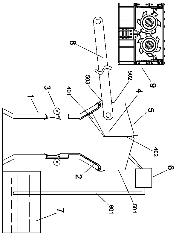
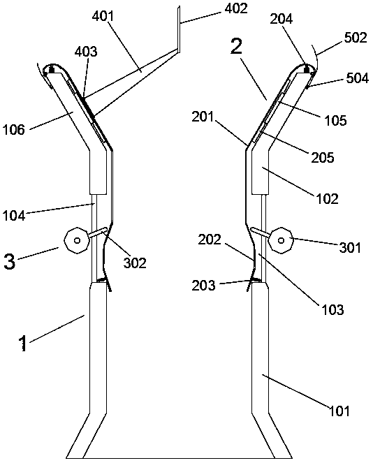
[0035] Such as figure 1 and 2 As shown, an upper and lower split anti-clogging type coal fall, the cylinder 1 of the coal fall includes a lower cylinder 101 and an upper cylinder 102 separated from each other, and between the lower cylinder 101 and the upper cylinder 102 Supported by several support columns 104, there are gaps between these support columns 104, thereby forming a grid-like partition 103 between the lower cylinder 101 and the upper cylinder 102, the existence of the grid-type partition 103 is mainly to In order to provide a knocking position; the inner wall of the upper cylinder 102 is provided with a smooth rubber cushion 201, the top of the smooth rubber cushion 201 is detachably fixed on the top of the upper cylinder 102, and the lower part extends beyond the grid partition 103 to carry out Fix and cover the inner wall of the grid-type partition 103, that is to say, the smooth rubber cushion layer 201 completely covers the grid-type partition 103 to prevent ...
Embodiment 2
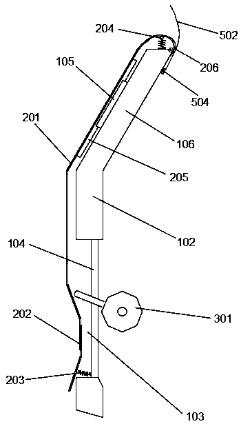
[0039] This embodiment is an improvement made on the basis of Embodiment 1, and its main structure is the same as that of Embodiment 1, the difference is that: figure 2 , 3 As shown in and 5, the upper end of the smooth rubber pad 201 goes around the top of the upper cylinder 102 and is fixed to its outer wall, and there are several support rods 204 supported by compression springs between the top of the upper cylinder 102 and the smooth rubber pad 201 , the support rod 204 pushes up the upper part of the smooth rubber pad 201 under the elastic force of the compression spring, so that it forms a sliding deformation part with the top end of the upper cylinder 102 .
[0040] The support rod 204 in this embodiment is actually an annular rod distributed along the top of the upper cylinder 102, and the lower part of the annular rod is supported by several compression springs. Of course, the annular rods can also be arc-shaped rods with gaps in the middle of several sections, but ...
Embodiment 3
[0042] This embodiment is a further improvement made on the basis of embodiment 2, and its main structure is the same as that of embodiment 2, the difference is that: figure 2 , 3 As shown in and 5, there are several sets of sliding support components between the smooth rubber pad 201 and the inner wall of the upper cylinder 102, and these sliding support components are evenly distributed around the central axis of the upper cylinder 102 and are parallel to the axial direction; The set of sliding support components includes U-shaped groove rails 105 evenly distributed on the inner wall around the central axis of the upper cylinder 102 and track bars 205 slidingly fitted with the U-shaped groove rails 105, and the track bars 205 are fixed on the smooth rubber pad 201 , so that the smooth rubber pad 201 moves under the constraints of the track bar 205 and the U-shaped groove track 105 when knocked.
[0043] In this embodiment, lubricating oil can be added between the U-shaped ...
PUM
 Abstract
Description
Claims
Application Information
 - R&D
- Intellectual Property
- Life Sciences
- Materials
- Tech Scout
- Unparalleled Data Quality
- Higher Quality Content
- 60% Fewer Hallucinations
Browse by: Latest US Patents, China's latest patents, Technical Efficacy Thesaurus, Application Domain, Technology Topic, Popular Technical Reports.
© 2025 PatSnap. All rights reserved.Legal|Privacy policy|Modern Slavery Act Transparency Statement|Sitemap|About US| Contact US: help@patsnap.com