Braking differential type rotor wing propeller fixed wing helicopter

A technology of helicopters and propellers, applied to rotorcraft, aircraft parts, aircraft control, etc., can solve problems such as accidents, fast horizontal flight speed, and large load capacity, and achieve the effect of reducing height

Inactive Publication Date: 2020-04-10
江富余
View PDF0 Cites 2 Cited by
  • Summary
  • Abstract
  • Description
  • Claims
  • Application Information

AI Technical Summary

Problems solved by technology

[0002] At present, there are known successful methods that can realize the helicopter that can use the airport to slide forward, or can not rely on the airport to adopt multi-rotor vertical lift, hover, front, back, left, and right flight. The tilt rotor has the advantage of large load capacity and horizontal flight. The speed is fast, and its disadvantage is that the rotor is set at both ends of the fixed wing, which requires high strength of the spar, and the rapid tilting of the huge rotor produces a large gyro force, which requires high strength of the tilting mechanism, and the horizontal structure of the rotor is easy. The vortex ring effect is generated and rolls to one side, causing accidents. The flight efficiency of the large propeller rotor is low

Method used


Image

  • Braking differential type rotor wing propeller fixed wing helicopter
  • Braking differential type rotor wing propeller fixed wing helicopter

Examples


Embodiment Construction

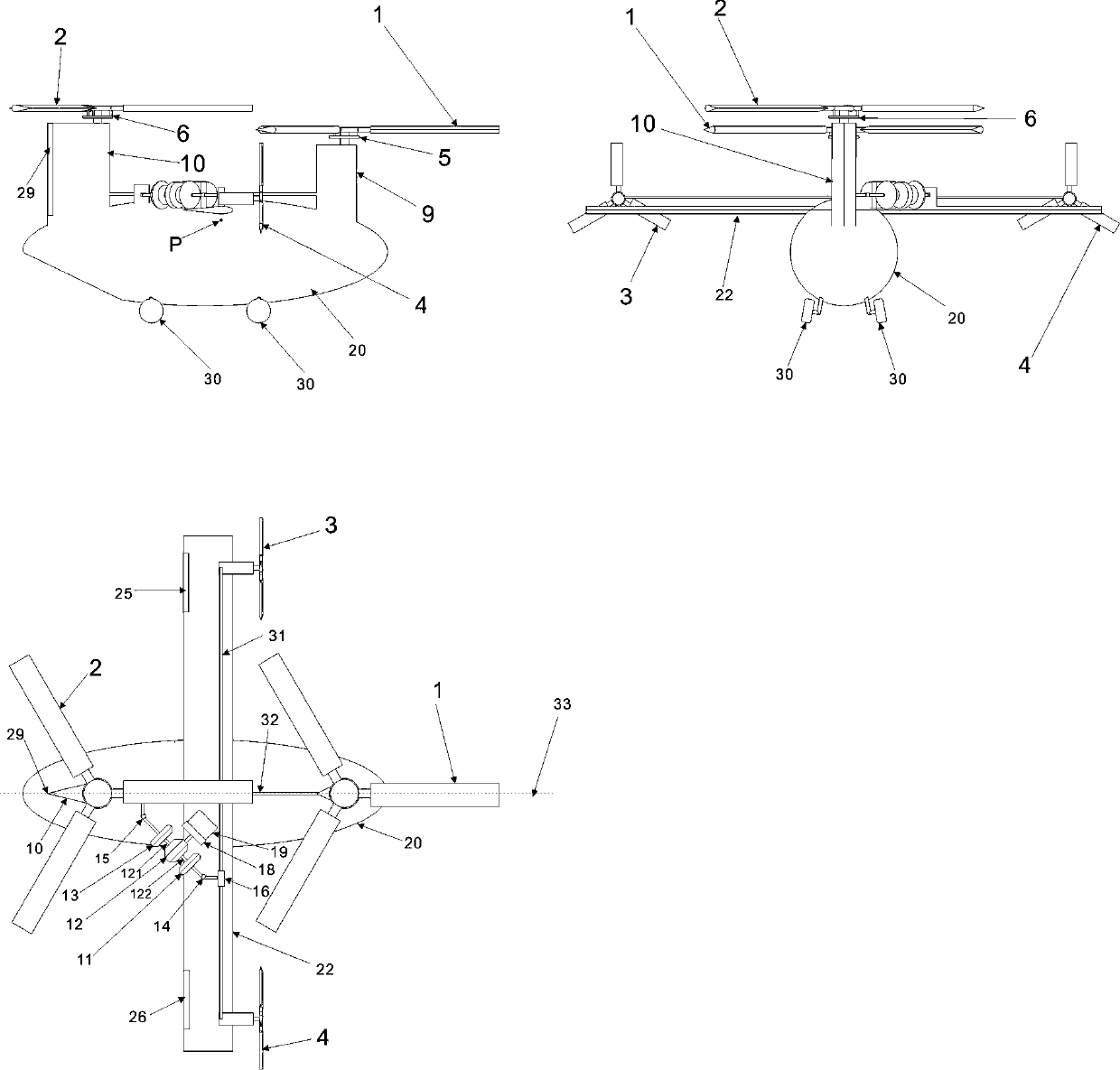
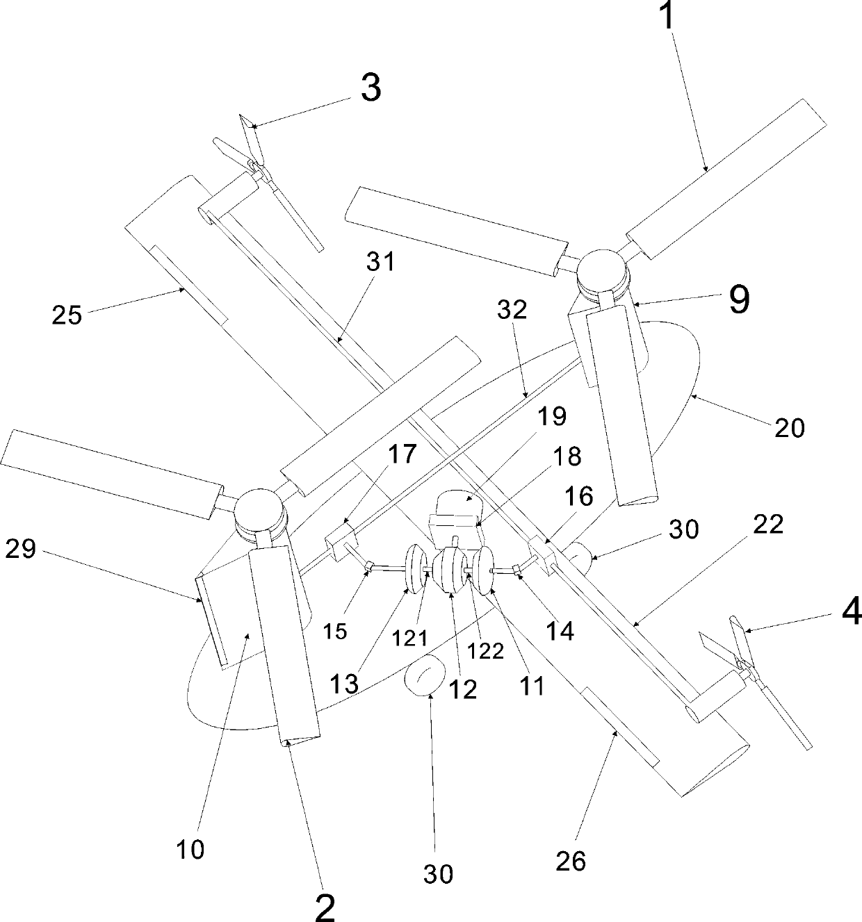
[0055] figure 1 In the shown embodiment, the two rotors adopt a tandem layout, and the fuselage (20) head is provided with the first small tower (9) of the airfoil, and the first small tower (9) of the airfoil acts as a vertical tail. The first rotor (1) is set on the type first small tower (9), and the airfoil second small tower (10) is set at the rear of the fuselage (20). The small tower plays the role of a vertical empennage. Set the second rotor (2) on (10).

[0056] The second small tower (10) is set higher than the first small tower (9), and the distance between the two small towers is greater than the radius of the rotor, which can reduce the impact of the front rotor downwash on the rear rotor.

[0057] The center of the line connecting the centers of rotation of the first rotor (1) and the second rotor (2) is on the center of gravity (P), and the line overlaps with the longitudinal line of the fuselage (33).

[0058] The vertical tail of the second small tower (10)...


PUM


Abstract

The invention discloses a braking differential type rotor wing propeller fixed wing helicopter. Two rotor wings are arranged on wing-shaped small towers at the head and the tail of a fuselage. The paddles of the rotor wings are connected with a rotor wing shaft through a paddle shell which is provided with a flapping hinge, a shimmy hinge and a variable-pitch hinge. A total pitch controller and aperiodic variable pitch controller are arranged to control the paddle pitch of the rotor wings. An upper single-wing fixed wing with high aspect ratio is arranged in the middle of the fuselage, and variable-pitch propellers are arranged on the left and right of the fixed wing. An engine is arranged to drive a differential mechanism through a gearbox and a clutch. A first output shaft of the differential mechanism drives the two rotors through an overrunning clutch, a universal shaft and a rotor synchronous reverser. A second output shaft of the differential mechanism drives the left and rightvariable-pitch propellers through an overrunning clutch, a universal shaft and a propeller synchronous reverser. A wheel type undercarriage is arranged, and different output shafts of the differentialmechanism are braked through a brake. The power of the engine is distributed to the rotor wings or variable-pitch propellers, and various flight modes of helicopters, fixed wings and autorotation rotor wings are freely switched. The helicopter has the advantages of being high in speed, low in energy consumption and suitable for taking-off and landing occasions requiring no airports.

Description

technical field [0001] The invention relates to a braking differential rotor propeller fixed-wing helicopter that can be pulled by a propeller and fly forward by taxiing at an airport, or can vertically lift, hover, and fly forward, backward, left, and right with multi-rotors independent of the airport. Background technique [0002] At present, there are known successful methods that can realize helicopters that can use the airport to slide forward, or can not rely on the airport to adopt multi-rotor vertical lift, hover, front, back, left, and right. The successful method is the tilt rotor, which has the advantage of large load capacity and horizontal flight. The speed is fast, and its disadvantage is that the rotor is set at both ends of the fixed wing, which requires high strength of the spar, and the rapid tilting of the huge rotor produces a large gyro force, which requires high strength of the tilting mechanism, and the horizontal structure of the rotor is easy The vor...

Claims


Application Information

Patent Timeline
Patent Type & Authority Applications(China)
IPC IPC(8): B64C27/08B64C27/32B64C27/12B64C9/20B64C9/00
CPCB64C9/00B64C9/20B64C27/08B64C27/12B64C27/32
Inventor 江富余
Owner 江富余
Why Eureka
Try Eureka