Drilling device

A technology for drilling devices and drill bits, which is applied to stone processing tools, work accessories, manufacturing tools, etc., and can solve the problems of reducing the reliability of drilling devices, poor practicability, and reducing drilling quality, etc.

Active Publication Date: 2020-04-10
武义科众电器有限公司
View PDF10 Cites 0 Cited by
  • Summary
  • Abstract
  • Description
  • Claims
  • Application Information

AI Technical Summary

Problems solved by technology

[0002] As we all know, the installation of water and electricity and air-conditioning are usually involved in the construction decoration project, and whether it is the installation of water and electricity or the installation of air-conditioning, it is usually necessary to drill holes in the wall of the building for the installation of water and electricity and air-conditioning. The pipes used provide manufacturing and installation adjustments. The drilling device is a device used to assist workers to drill holes in designated parts of the building wall in the process of hydropower installation or air-conditioning installation. It has been widely used in the field of body drilling; the existing drilling device includes a power mechanism, a drill bit and a hand-held assembly. A switch control component is provided; when the existing drilling device is used, the drilling mark is first made on the designated drilling part of the wall of the building decoration project, and then the staff lifts the power mechanism through the hand-held component, and starts The power mechanism makes the output end of the power mechanism drive the drill bit to rotate quickly, and then the drill bit is aligned with the drilling mark to drill the hole; it is found in the use of the existing drilling device that due to human factors, the staff manually controls the drilling When the drill bit of the device is drilling, the drill bit is prone to skewing, thus reducing the quality of the drilling, thereby reducing the reliability of the drilling device, resulting in poor practicability

Method used


Image

  • Drilling device
  • Drilling device
  • Drilling device

Examples


Embodiment Construction

[0019] The specific implementation manners of the present invention will be further described in detail below in conjunction with the accompanying drawings and embodiments. The following examples are used to illustrate the present invention, but are not intended to limit the scope of the present invention.

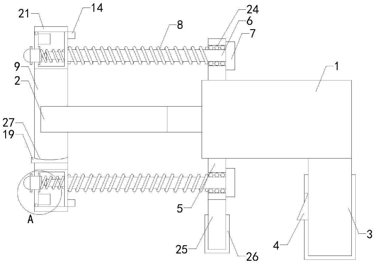
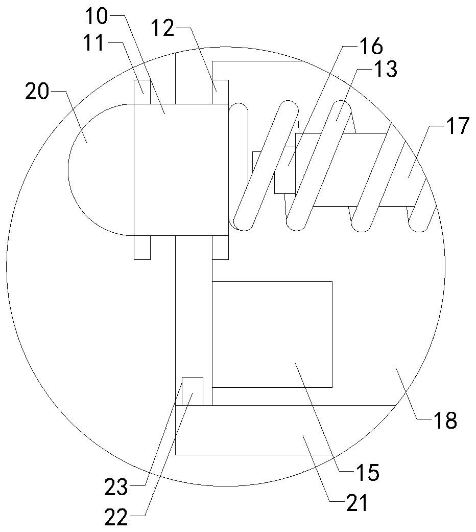
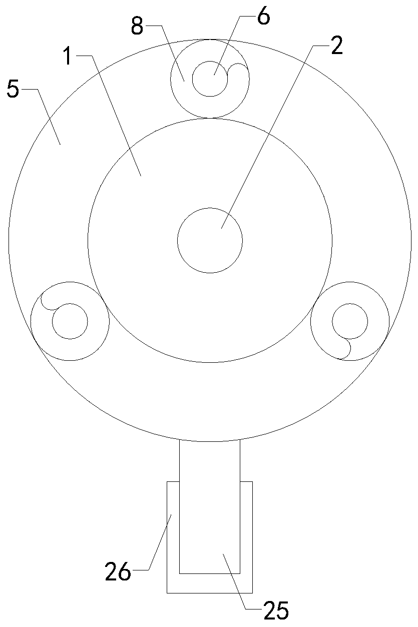
[0020] Such as Figure 1 to Figure 5As shown, a drilling device of the present invention includes a power mechanism 1, a drill bit 2 and a hand-held assembly 3, the drill bit 2 is installed at the output end of the power mechanism 1, the hand-held assembly 3 is installed at the right end of the bottom area of ​​the power mechanism 1, and the hand-held assembly 3 is provided with a switch control assembly 4; it also includes a fixed ring 5, three sets of telescopic rods 6, three sets of baffles 7, three sets of control springs 8, a limit ring 9, three sets of extrusion blocks 10, and three sets of left protective rings 11. Three sets of right protective rings 12, three set...


PUM


Abstract

The invention relates to the technical field of accessory devices of building decoration equipment, in particular to a drilling device. A drilling path of a drill bit can be limited, thus the probability that the drill bit declines is reduced, the drilling quality is improved, and the use reliability of the drilling device is improved. The drilling device comprises a power mechanism, the drill bitand a handheld assembly. The drill bit is installed at the output end of the power mechanism. The handheld assembly is installed at the right end of the bottom area of the power mechanism. The handheld assembly is provided with a switch control assembly. The drilling device further comprises a fixing ring, three telescoping rods, three baffles, three control springs, a limiting ring, three extruding blocks, three left protecting rings, three right protecting rings, three resetting springs, three indicator lamp assemblies, three battery assemblies, three non-self-locking button switch assemblies and three installing rods. Three working grooves are formed in the top end of the outer side wall of the limiting ring, the front side of the bottom area and the rear side of the bottom area correspondingly.

Description

technical field [0001] The invention relates to the technical field of accessory devices of building decoration equipment, in particular to a drilling device. Background technique [0002] As we all know, the installation of water and electricity and air-conditioning are usually involved in the construction decoration project, and whether it is the installation of water and electricity or the installation of air-conditioning, it is usually necessary to drill holes in the wall of the building for the installation of water and electricity and air-conditioning. The pipes used provide manufacturing and installation adjustments. The drilling device is a device used to assist workers to drill holes in designated parts of the building wall in the process of hydropower installation or air-conditioning installation. It has been widely used in the field of body drilling; the existing drilling device includes a power mechanism, a drill bit and a hand-held assembly. A switch control co...

Claims


Application Information

Patent Timeline
Patent Type & Authority Applications(China)
IPC IPC(8): B28D1/14B28D7/00B28D7/02
CPCB28D1/146B28D7/00B28D7/02
Inventor 李晓艳刘毓敏
Owner 武义科众电器有限公司
Why Eureka
Try Eureka