Concrete stirring and mixing device used for construction site of building site

A technology for construction sites and construction sites, which is applied to the field of concrete mixing and mixing devices on construction sites, can solve problems such as unrealistic, inability to meet processing requirements, and inability to guarantee mixing and mixing quality, so as to improve construction quality and avoid uneven mixing. Effect

Inactive Publication Date: 2020-04-10
李付民
View PDF14 Cites 3 Cited by
  • Summary
  • Abstract
  • Description
  • Claims
  • Application Information

AI Technical Summary

Problems solved by technology

[0003] Most of the current concrete mixing devices adopt a single-driven mixing method, such as a kind of construction mixer that can be uniformly stirred in Chinese Patent Publication No. CN108582490A, and a kind of construction cement mixer in Chinese Patent Publication No. CN108515614A. The rod is used to turbulence, but the raw materials are still stirred in one direction, and this shaft stirring method is completely unrealistic for a large amount of cement mixing work, which cannot meet the processing requirements and cannot guarantee the quality of mixing

Method used


Image

  • Concrete stirring and mixing device used for construction site of building site
  • Concrete stirring and mixing device used for construction site of building site
  • Concrete stirring and mixing device used for construction site of building site

Examples


Embodiment 1

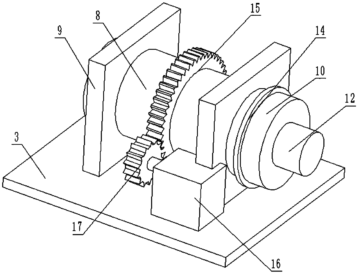
[0019] see Figure 1-3 , a concrete mixing device for a construction site, comprising a frame 1, a turret 3 and a mixing drum, the turret 3 is located above the frame 1, and the bottom of the frame 1 is provided with a plurality of moving wheels 2, and the mixing drum Located above the turret 3, the mixing cylinder includes a fixed cylinder 10 and a rotating cylinder 8, the rotating cylinder 8 is connected to the fixed cylinder 10 in rotation, the fixed cylinder 10 is fixed on the turret 3 through a bracket, and a feeding cylinder is provided on the top of the fixed cylinder 10 13. A number of drum brackets 9 are also provided on the turret 3, and the drum brackets 9 are set on the outside of the rotating drum 8 and connected in rotation with the rotating drum 8. A second drive motor 16 is arranged on the top surface of the turret 3, and the second The output end of drive motor 16 is provided with drive gear 17, is provided with suit gear ring 15 on the outer wall of rotating ...

Embodiment 2

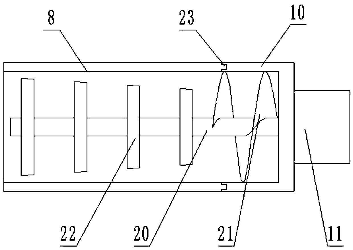
[0024] On the basis of Embodiment 1, in order to further facilitate the output of raw materials and ensure the sufficient mixing of concrete, a push auger 21 is provided on the drive shaft 20, and the push auger 21 is located in the fixed cylinder 10, and the push auger The outer side of 21 fits and is slidably connected to the inner wall of the fixed cylinder 10. During the stirring process, the raw material first enters the fixed cylinder 10 through the feeding cylinder 13. At this time, the first driving motor 11 drives the drive shaft 20 to work, and the driving shaft 20 is driven by the pushing auger 21. The raw materials can be transported into the rotating cylinder 8, so that the raw materials can obtain a two-way stirring effect, and in the process of conveying the raw materials to the rotating cylinder 8 through the pushing auger 21, the raw materials are carried out by the pushing auger 21 and the inner wall of the fixed cylinder 10. Extrusion avoids agglomeration cau...

Embodiment 3

[0026] On the basis of Embodiment 1, in order to ensure the stable operation of the equipment, a plurality of buffer spring columns 7 are provided between the frame 1 and the turret 3, and the buffer spring columns 7 are fixed on the frame 1, and the buffer The top of the spring column 7 is provided with a rubber pad. When stirring, the shock can be absorbed and buffered by the buffer spring column 7 to avoid equipment damage, and when the turret 3 is rotated and retracted, the impact force can also be absorbed by the buffer spring column 7 , to ensure the safety of the equipment.


PUM


Abstract

The invention discloses a concrete stirring and mixing device used for a construction site of a building site. The concrete stirring and mixing device comprises a rack, a rotating frame and a stirringcylinder, the rotating frame is located above the rack, a plurality of moving wheels are arranged at the bottom of the rack, the stirring cylinder is located above the rotating frame, the stirring cylinder comprises a fixed cylinder and a rotating cylinder, the rotating cylinder is rotationally connected with the fixed cylinder, the fixed cylinder is fixed to the rotating frame through a support,a feeding cylinder is arranged at the top of the fixed cylinder, a plurality of rotating cylinder supports are further arranged on the rotating frame, the rotating cylinder supports sleeve on the outer part of the rotating cylinder and are rotationally connected with the rotating cylinder, a second driving motor is arranged on the top face of the rotating frame, and a driving gear is arranged atthe output end of the second driving motor. According to the concrete stirring and mixing device for the construction site of the building site, when stirring and mixing concrete by the device are carried out, and a first driving motor is started to drive a driving shaft and the rotating cylinder to reversely rotate, so that the stirring and mixing work of the concrete is quickly realized throughthe rotation in two opposite directions, the phenomenon of non-uniform stirring caused by single rotation is avoided, and the later construction quality is improved.

Description

technical field [0001] The invention relates to building construction equipment, in particular to a concrete stirring and mixing device for the construction site of a construction site. Background technique [0002] Mixer is a kind of construction machinery, which is mainly used for mixing cement, sand, various dry powder mortar and other building materials. It is a shaft with blades that rotates in a cylinder or a tank to mix various raw materials. , to make a mixture or a machine of suitable consistency. There are many kinds of mixers, such as forced mixers, single horizontal shaft mixers and so on. Construction sites need to use mixers to mix concrete during construction. [0003] Most of the current concrete mixing devices adopt a single-driven mixing method, such as a kind of construction mixer that can be uniformly stirred in Chinese Patent Publication No. CN108582490A, and a kind of construction cement mixer in Chinese Patent Publication No. CN108515614A. The rod i...

Claims


Application Information

Patent Timeline
IPC IPC(8): B28C5/24
CPCB28C5/0831B28C5/2045B28C5/24
Inventor 李付民
Owner 李付民
Why Eureka
Try Eureka