
Lifting and rotating device for horizontal cam exchange table

A technology of lifting, rotating and exchanging tables, which is applied in the direction of large fixed members, metal processing machinery parts, metal processing equipment, etc., can solve the problems of limiting operation efficiency and slow driving speed of hydraulic lifting, and achieve the effect of improving operation efficiency

Pending Publication Date: 2020-04-10
SUZHOU FURUTA AUTOMATION TECH
View PDF0 Cites 5 Cited by
  • Summary
  • Abstract
  • Description
  • Claims
  • Application Information

AI Technical Summary

Problems solved by technology

At present, the lifting and rotating device is usually driven by hydraulic pressure, which needs to be equipped with a hydraulic station, and the speed of the hydraulic lifting drive is relatively slow when lifting and rotating, which limits the improvement of operating efficiency

Method used


Image

  • Lifting and rotating device for horizontal cam exchange table
  • Lifting and rotating device for horizontal cam exchange table
  • Lifting and rotating device for horizontal cam exchange table

Examples


Embodiment Construction

[0018] In order to understand the technical content of the present invention more clearly, the following examples are given in detail, the purpose of which is only to better understand the content of the present invention but not to limit the protection scope of the present invention. The components in the structures in the drawings of the embodiments are not scaled according to the normal scale, so they do not represent the actual relative sizes of the structures in the embodiments. The above or upper side of the structure or surface includes the case where there are other layers in the middle.

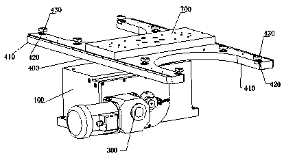
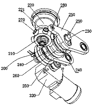
[0019] Such as figure 1 , figure 2 , image 3 , Figure 4 , Figure 5 , Figure 6 and Figure 7As shown, a lifting and rotating device for a horizontal cam exchange table, a lifting and rotating device for a horizontal cam exchange table, including a box body 100, a cam transmission mechanism 200, a driving mechanism 300 and a rotating plate 400, on the box body A first insta...


PUM


Abstract

The invention discloses a lifting and rotating device for a horizontal cam exchange table. The lifting and rotating device comprises a box body, a cam transmission mechanism, a driving mechanism and arotating plate, the cam transmission mechanism is installed in the box body, and the cam transmission mechanism comprises a center shaft, an output shaft, a force input shaft, two flat cams, two rocker arms and a globoidal cam; the cam transmission mechanism realizes lifting and rotating functions; the driving mechanism is used for providing rotating power for the cam transmission mechanism; therotating plate is used for supporting and positioning a rotary workbench of a cam roller rotary table and a rotary workbench of a preparation tool, a jacking convex seat and a jacking concave seat arranged on the rotary plate are matched with each other, and the rotary workbench can be positioned at a U-shaped arm of the rotary plate in the lifting process and can be easily separated from the rotary workbench after rotating. The lifting and rotating functions are achieved, the sectional speed can be adopted for lifting and rotating, a hydraulic station does not need to be arranged, and the operation efficiency is greatly improved.

Description

technical field [0001] The invention relates to the technical field of cam roller turntables, in particular to a lifting and rotating device for a horizontal cam exchange table. Background technique [0002] CNC rotary table, also known as turntable, can be divided into worm gear and worm drive turntable and cam roller turntable according to different transmission modes. The cam roller turntable can eliminate the transmission gap inside the turntable and improve the accuracy of the workpiece during processing. The stability of the rotary motion of the turntable; it has the product characteristics of low friction, no gap, and strong rigidity. Therefore, the cam roller rotary table is widely used in machining centers such as milling machines and drilling machines. The cam roller turret usually includes a box body, a rotary table mounted on the box body through a rotary output shaft, a cam roller transmission mechanism and a drive motor for transmission to the rotary output ...

Claims


Application Information

Patent Timeline
IPC IPC(8): B23Q1/66
CPCB23Q1/66
Inventor 赵相雨邱海涛
Owner SUZHOU FURUTA AUTOMATION TECH
Learn More