Electrostatic dust collector based on non-uniform electric field

A technology of electrostatic dust collection and uniform electric field, applied in the field of dust removal, can solve the problems of secondary pollution of the environment, serious secondary pollution, high energy consumption of the device, and achieve the effects of avoiding secondary pollution, improving efficiency, and low energy consumption

Active Publication Date: 2021-12-07
付聪
View PDF7 Cites 0 Cited by
  • Summary
  • Abstract
  • Description
  • Claims
  • Application Information

AI Technical Summary

Problems solved by technology

[0003] The currently used electrostatic precipitator mainly makes free electrons attach to the dust particles by breaking down the air discharge, but there are several problems in using this method: first, ozone is bound to be generated in the process of breaking down the air, Secondary pollution to the environment; the second is to use the method of breaking down the air. The discharge capacity is large enough to ensure that enough dust particles can be charged. If the power is small, some dust particles cannot be charged, but the greater the discharge capacity, The greater the amount of ozone in the air, the more serious the secondary pollution will be; the third is that it is difficult for the dust removal device to completely absorb the generated charge, and the unabsorbed charge leaves the dust removal device with the fresh air, making the fresh air charged, which is different from the neutral air. The normal air is potentially dangerous; the fourth is that the entire device needs to be continuously discharged during use, which makes the overall energy consumption of the device higher
Although this device can realize the rapid cleaning of dust, the dust collection still uses the method of breaking down the air to make the dust particles stick to free electrons.

Method used


Image

  • Electrostatic dust collector based on non-uniform electric field
  • Electrostatic dust collector based on non-uniform electric field
  • Electrostatic dust collector based on non-uniform electric field

Examples


Embodiment 1

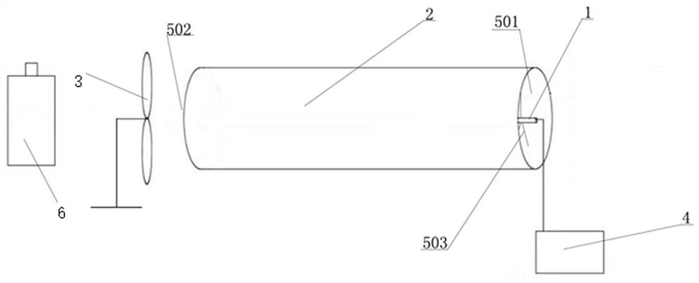
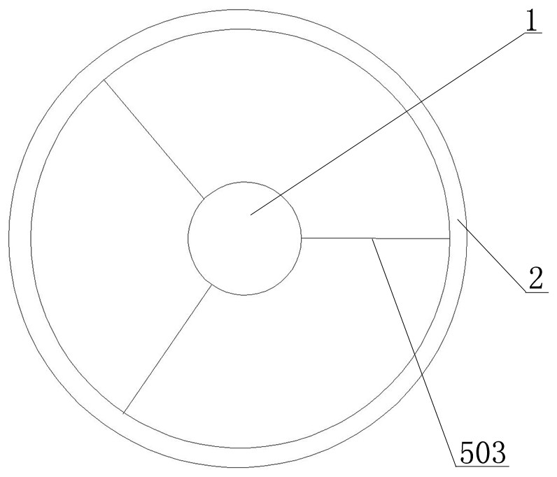
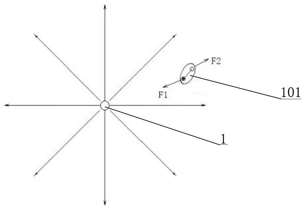
[0030] to combine Figure 1 to Figure 4 , an electrostatic dust collection device based on a non-uniform electric field, including a dust collection electrode 1, a shielding pipe 2 and a fan 3, the shielding pipe 2 is coaxially sleeved on the outside of the dust collection electrode 1 through an electrode support assembly, and the dust collection electrode 1 is connected to After the high-voltage power supply 4 and the dust-collecting electrode 1 are connected to the high-voltage power supply 4, a non-uniform electric field radiating outward is formed, and the dust-collecting electrode 1 is connected and fixed to the shielding tube 2 by using the electrode support assembly, and at the same time, the shielding tube 2 is grounded to ensure The non-uniform electric field generated by the dust collecting electrode 1 is free from external interference.

[0031] An electrode dust collection channel through which dust-containing gas passes is formed between the shielding tube 2 and t...

Embodiment 2

[0045] combine Figure 5 The difference between this embodiment and the first embodiment is that in this embodiment, the dust collecting electrode 1, the shielding tube 2 and the electrode support assembly form the electrostatic dust collection unit in the electrostatic dust collection device, and the electrostatic dust collection units are arranged in parallel, The axes of each group of electrostatic precipitating units are parallel to each other, and the shielding tubes 2 in each electrostatic precipitating unit are connected through conductors 7 .

[0046] The device can be implemented in a large-scale use environment and improve the overall dust collection efficiency. Among them, the adjacent shielding tubes 2 in each electrostatic dust collection unit are connected by a conductor 7, so that each shielding tube 2 forms an equipotential body , the electric fields in each group of electrostatic dust collection units do not interfere with each other because of the effect of e...

Embodiment 3

[0048] combine Image 6 , The difference between this embodiment and Embodiment 1 is that: the shielding tubes are multiple cylinders arranged in concentric circles, and the outermost shielding tube is grounded.

[0049] Further, the shielding tubes are sequentially arranged radially outward from the dust collecting electrode 1, and the adjacent shielding tubes 2 are connected by the shielding tube support assembly, and the dust collection channel of the shielding tube is formed between the adjacent shielding tubes, and the shielding tubes Both ends of the dust collection channel are open, and together with the opening ends of the electrode dust collection channel respectively form an air outlet and an air inlet in this embodiment.

[0050] Further, the shielding tube support assembly is arranged at both ends of the dust collection channel of the shielding tube, that is, at the ends of the air outlet and the air inlet.

[0051] Further, there are three shielding tube support ...


PUM


Abstract

The invention discloses an electrostatic dust collection device based on a non-uniform electric field, which includes a dust collection electrode, a shielding pipe and a fan. The shielding pipe is coaxially sleeved on the outside of the dust collection electrode through an electrode support assembly, and the dust collection electrode is connected to a high-voltage power supply. An electrode dust-collecting channel through which dust-containing gas passes is formed between the shielding tube and the dust-collecting electrode. Both ends of the electrode dust-collecting channel are open. One end of the electrode dust-collecting channel is an air inlet, and the other end is an air outlet. There is a fan on the outside that brings the dust-laden gas into the dust-collecting channel of the electrode; the dust-collecting electrode, the shielding tube and the support assembly form the electrostatic dust-collecting unit in the electrostatic dust-collecting device, and the electrostatic dust-collecting units are arranged in parallel; The shielding tube is a multi-tube shape arranged in concentric circles, and is arranged in increasing order from the dust collecting electrode radially outward. The invention can realize gas dust collection under the premise of not breaking through the air, has simple device structure, low energy consumption, does not generate ozone, and avoids secondary pollution.

Description

technical field [0001] The invention belongs to the technical field of dust removal, and in particular relates to an electrostatic dust collection device based on a non-uniform electric field. Background technique [0002] The electrostatic precipitator is a dust removal device that uses the Coulomb force to separate the dust or liquid droplets in the gas to achieve the effect of purifying the air. It has a wide range of applications in industrial production and households. [0003] The currently used electrostatic precipitator mainly makes free electrons attach to the dust particles by breaking down the air discharge, but there are several problems in using this method: first, ozone is bound to be generated in the process of breaking down the air, Secondary pollution to the environment; the second is to use the method of breaking down the air. The discharge capacity is large enough to ensure that enough dust particles can be charged. If the power is small, some dust particl...

Claims


Application Information

Patent Timeline
Patent Type & Authority Patents(China)
IPC IPC(8): B03C3/02B03C3/06B03C3/36
CPCB03C3/025B03C3/06B03C3/368
Inventor 付聪付宏
Owner 付聪
Why Eureka
Try Eureka