
Float flowmeter

A float flow meter and flow meter technology, which is applied in the direction of buoy liquid level indicator, etc., can solve the problems of inability to achieve accurate measurement, inability to meet the requirements of the digital hospital era, and high power consumption.

Pending Publication Date: 2020-04-07
BEIJING HAIHUI TELECOMM TECH
View PDF0 Cites 0 Cited by
  • Summary
  • Abstract
  • Description
  • Claims
  • Application Information

AI Technical Summary

Problems solved by technology

[0003] The first type is the mechanical oxygen flowmeter, which uses a mechanical device to estimate the instantaneous gas flow rate by a simple scale scale, which cannot achieve accurate measurement results, especially for small flow gas.
It can't even realize the purpose of digital measurement and digital management, and can't meet the requirements of the era of digital hospitals
[0004] The second type is the heating type thermistor bridge flow sensor, which adopts a heating wire in the gas circuit and installs thermistors on both sides. When the air flow passes through, the resistance of the thermistor in the bridge changes, resulting The bridge is unbalanced, the output sampling voltage is obtained, and the oxygen flow rate at the reaction site changes. This device consumes a lot of power and has high manufacturing costs, so it is not suitable for general promotion.

Method used


Image

  • Float flowmeter
  • Float flowmeter
  • Float flowmeter

Examples


Embodiment Construction

[0026] Embodiments of the present application are specifically described below with reference to the accompanying drawings.

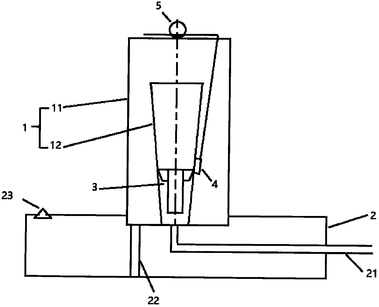
[0027] figure 1 One embodiment of the rotameter of the present application is shown. As shown in the figure, in general, the float flowmeter according to the present application includes: a flowmeter body 1 , a gas supply device 2 , a float 3 , a Hall element 4 , and a position holder 5 .

[0028] First, the flow meter body 1 will be described. The flowmeter body 1 has an inner casing 12, an air inlet, and an air outlet. In use, gas is passed directly into the inner housing 12 where the gas is metered by the float 3 in the inner housing 12 .

[0029] The flowmeter body 1 may also include an outer casing 11 . The outer casing 11 is surrounded by the inner casing 12, and the gas enters the inner casing 12 from the air inlet, passes through the float 3, and is discharged from the inner casing 12 to the outer casing 11, and then is discharged to the exh...


PUM


Abstract

A float flowmeter is characterized in that the float flowmeter comprises a flowmeter body, the flowmeter body being provided with an inner shell, an outer shell, a gas inlet and a gas outlet, the outer shell surrounding the inner shell, and gas sequentially passing through the gas inlet, the inner shell, the outer shell and the gas outlet and flowing through the flowmeter body; a floater, locatedin the containing space in the inner shell and can move in the flow meter body under the action of gas passing through the flow meter body, and the floater being provided with a magnetic part; and a Hall element, located on the side wall of the inner shell of the flow meter body and used for detecting the position of the magnetic part of the floater.

Description

technical field [0001] The present application relates to a gas flow measuring device, in particular to a device for digitally collecting oxygen flow at the bedside of a hospital. Background technique [0002] At present, there are two main types of devices on the market for measuring oxygen flow at the patient's bedside, one is a mechanical float flowmeter, and the other is an electronic oxygen flowmeter: [0003] The first type is the mechanical oxygen flowmeter, which uses a mechanical device to estimate the instantaneous gas flow rate by a simple scale scale, which cannot achieve accurate measurement results, especially for small flow gas. Even more, it cannot realize the purpose of digital measurement and digital management, and cannot meet the requirements of the era of digital hospitals. [0004] The second type is the heating type thermistor bridge flow sensor, which adopts a heating wire in the gas circuit and installs thermistors on both sides. When the air flow p...

Claims


Application Information

Patent Timeline
Patent Type & Authority Applications(China)
IPC IPC(8): G01F23/72
CPCG01F23/72
Inventor 许泽民周尔范
Owner BEIJING HAIHUI TELECOMM TECH
Learn More