Internal combustion engine cooling system, control method and vehicle

A cooling system and internal combustion engine technology, applied in the field of vehicles, can solve the problems of reducing the life of the internal combustion engine, large deformation of the cylinder block, and uneven temperature, so as to prevent excessive deformation, avoid uneven shrinkage, and improve heat dissipation energy efficiency.

Active Publication Date: 2021-11-12
GREAT WALL MOTOR CO LTD
View PDF7 Cites 0 Cited by
  • Summary
  • Abstract
  • Description
  • Claims
  • Application Information

AI Technical Summary

Problems solved by technology

[0004] However, when the internal combustion engine is working, the temperature of the cylinder block is not uniform. In the existing cooling system, due to the unreasonable structure of the water jacket, the coolant will be directly connected to each cylinder block with the water jacket under the guidance of the water jacket. Parts contact, resulting in uneven stress everywhere in the cylinder block, large deformation of the cylinder block, affecting the normal operation of the internal combustion engine and reducing the life of the internal combustion engine

Method used


Image

  • Internal combustion engine cooling system, control method and vehicle
  • Internal combustion engine cooling system, control method and vehicle
  • Internal combustion engine cooling system, control method and vehicle

Examples


Embodiment 1

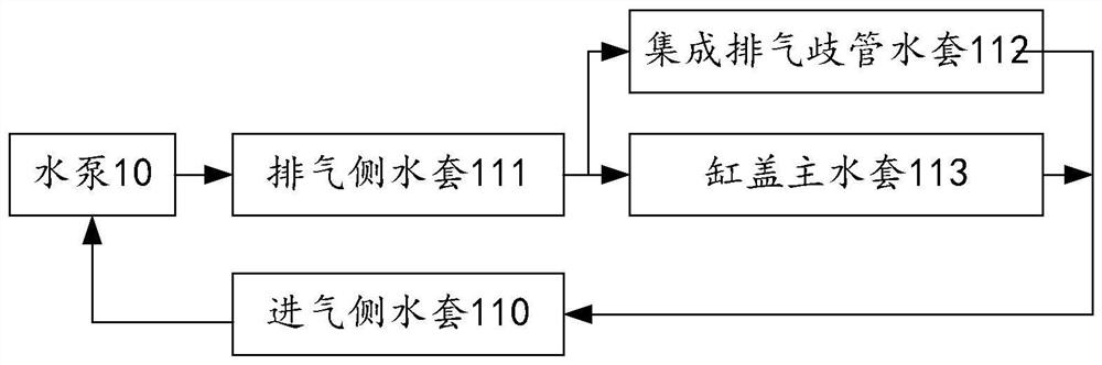
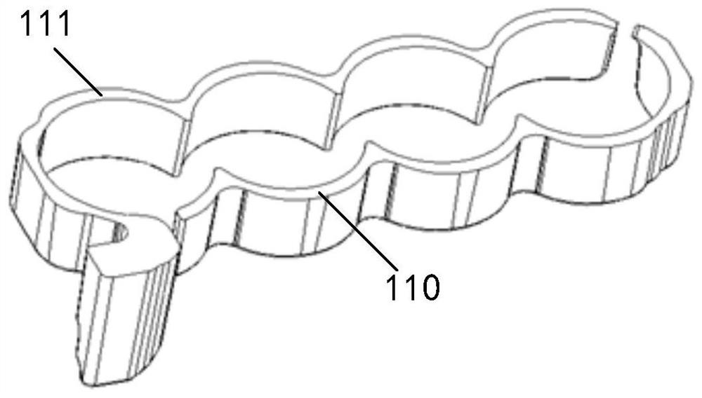
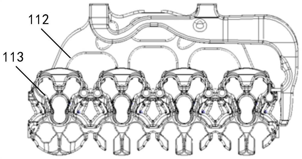
[0046] refer to Figure 1 to Figure 2-2 , provides a schematic diagram of the principle of an internal combustion engine cooling system of the present invention, the internal combustion engine cooling system includes a water pump 10 and an internal combustion engine cylinder block, and the internal combustion engine cylinder block is provided with an intake side water jacket 110 and an exhaust side water jacket 111 , Integrated exhaust manifold water jacket 112 and cylinder head main water jacket 113;

[0047] The water outlet of the water pump 10 is connected to the exhaust side water jacket 111, and the coolant is pumped to the exhaust side water jacket 111 by the water pump 10 for cooling the exhaust side of the cylinder block ;

[0048] The exhaust side water jacket 111 is connected to the cylinder head main water jacket 113 and the integrated exhaust manifold water jacket 112 at the same time, and the cylinder head main water jacket 113 is connected to the integrated exh...

Embodiment 2

[0053] refer to image 3 , diagram 2-1 and Figure 2-2 , provides a schematic diagram of the principle of an internal combustion engine cooling system of the present invention, the internal combustion engine cooling system includes a water pump 10 and an internal combustion engine cylinder block, and the internal combustion engine cylinder block is provided with an intake side water jacket 110 and an exhaust side water jacket 111 , Integrated exhaust manifold water jacket 112 and cylinder head main water jacket 113;

[0054] The water outlet of the water pump 10 is connected to the exhaust-side water jacket 111, and the coolant is pumped to the exhaust-side water jacket 111 by the water pump 10 for cooling the exhaust side of the cylinder block;

[0055] The exhaust side water jacket 111 is connected to the cylinder head main water jacket 113 and the integrated exhaust manifold water jacket 112 at the same time, and the cylinder head main water jacket 113 is connected to th...

Embodiment 3

[0069] refer to Figure 4 , the present invention provides a cooling control method for an internal combustion engine, the method comprising:

[0070] Step 101, pump the coolant to the water jacket on the exhaust side through the water pump to cool the exhaust side of the cylinder block;

[0071] Step 102, the coolant in the water jacket on the exhaust side enters the main water jacket of the cylinder head and the water jacket of the integrated exhaust manifold respectively in two routes according to a preset ratio, and is used to cool the cylinder head and the integrated exhaust manifold respectively. tube cooling;

[0072] Step 103 , the coolant in the cylinder head main water jacket and the integrated exhaust manifold water jacket converges into the intake side water jacket for cooling the intake side of the cylinder block.

[0073] A cooling method for an internal combustion engine according to the present invention is based on the aforementioned internal combustion engi...


PUM


Abstract

The invention provides a cooling system for an internal combustion engine. The system includes a water pump and a cylinder block of the internal combustion engine. The cylinder block of the internal combustion engine is provided with an intake side water jacket, an exhaust side water jacket, an integrated exhaust manifold water jacket and a cylinder head main water jacket. ;The water outlet of the water pump is connected to the water jacket of the exhaust side, and the coolant is pumped to the water jacket of the exhaust side through the water pump; the water jacket of the exhaust side is connected to the main water jacket of the cylinder head and the water jacket of the integrated exhaust manifold at the same time. The cover main water jacket and the integrated exhaust manifold water jacket form two parallel water paths; the cylinder head main water jacket and the integrated exhaust manifold water jacket are connected to the intake side water jacket at the same time. In the invention, the water jacket is divided into zones, and a new cooling circulating water circuit is constructed through the water jackets of different zones, and the temperature of the area with higher temperature is cooled first, and then the temperature of the area with lower temperature is cooled, so as to avoid the unevenness of each part of the cylinder body. Shrinkage, preventing excessive deformation, improving structural stability and service life.

Description

technical field [0001] The invention relates to the technical field of vehicles, in particular to an internal combustion engine cooling system, a control method and a vehicle. Background technique [0002] As the power plant of the vehicle, the internal combustion engine is at a suitable working temperature is very important to ensure the structural stability and working reliability of the internal combustion engine. [0003] At present, the temperature control of the internal combustion engine is usually to install an integral water jacket structure on the cylinder block, through which the cooling fluid circulating in the water jacket absorbs the heat emitted by the internal combustion engine cylinder block, reduces the temperature of the internal combustion engine, and prevents the overheating of the internal combustion engine's moving parts due to high temperature expansion. Cooperate with the gap to avoid high temperature failure of lubricating oil. [0004] However, wh...

Claims


Application Information

Patent Timeline
Patent Type & Authority Patents(China)
IPC IPC(8): F01P3/20F01P7/16
CPCF01P3/20F01P7/165
Inventor 常培松张春辉曹永伟赵华夏朝辉崔鹏程魏永强徐天博石鹏伟王浩门帅张瑞铺
Owner GREAT WALL MOTOR CO LTD
Why Eureka
Try Eureka