
Hydraulic fishing tool

A fishing tool and hydraulic technology, applied in wellbore/well parts, earthwork drilling and production, etc., can solve problems such as poor drillability, complicated operation, and difficulty in lifting out falling objects

Inactive Publication Date: 2020-04-07
CNPC DRILLING RES INST
View PDF0 Cites 2 Cited by
  • Summary
  • Abstract
  • Description
  • Claims
  • Application Information

AI Technical Summary

Problems solved by technology

[0002] With the continuous development of unconventional oil and gas resources, the drilling depth is getting deeper and deeper, and the well type is becoming more and more complex. There are more and more complexities in the drilling process. In some formations, the dip angle is large, the drillability is poor, and the formation In some formations with strong abrasiveness, the drill string is easy to wear and tear in some formations in the build-up section, eventually resulting in the breakage of the drilling tool and fish falling into the well; in addition, accidents of wire rope breakage sometimes occur during the electrical testing of well completion However, the salvage of the falling objects in the well is not ideal, and the falling objects are difficult to lift out, resulting in sidetracking of the injection plug
[0003] Some existing fishing tools are of fixed size or fixed purpose, and can only fish tools with a certain outer diameter, and generally they are columnar objects, and cannot handle some small, soft and irregularly shaped downhole objects like cables. To carry out effective salvage, and the operation is complicated, the success rate is low, and the time is long

Method used


Image

  • Hydraulic fishing tool
  • Hydraulic fishing tool
  • Hydraulic fishing tool

Examples


Embodiment Construction

[0018] Below in conjunction with three accompanying drawings of the present invention carry out the complete operation process description to hydraulic fishing tool

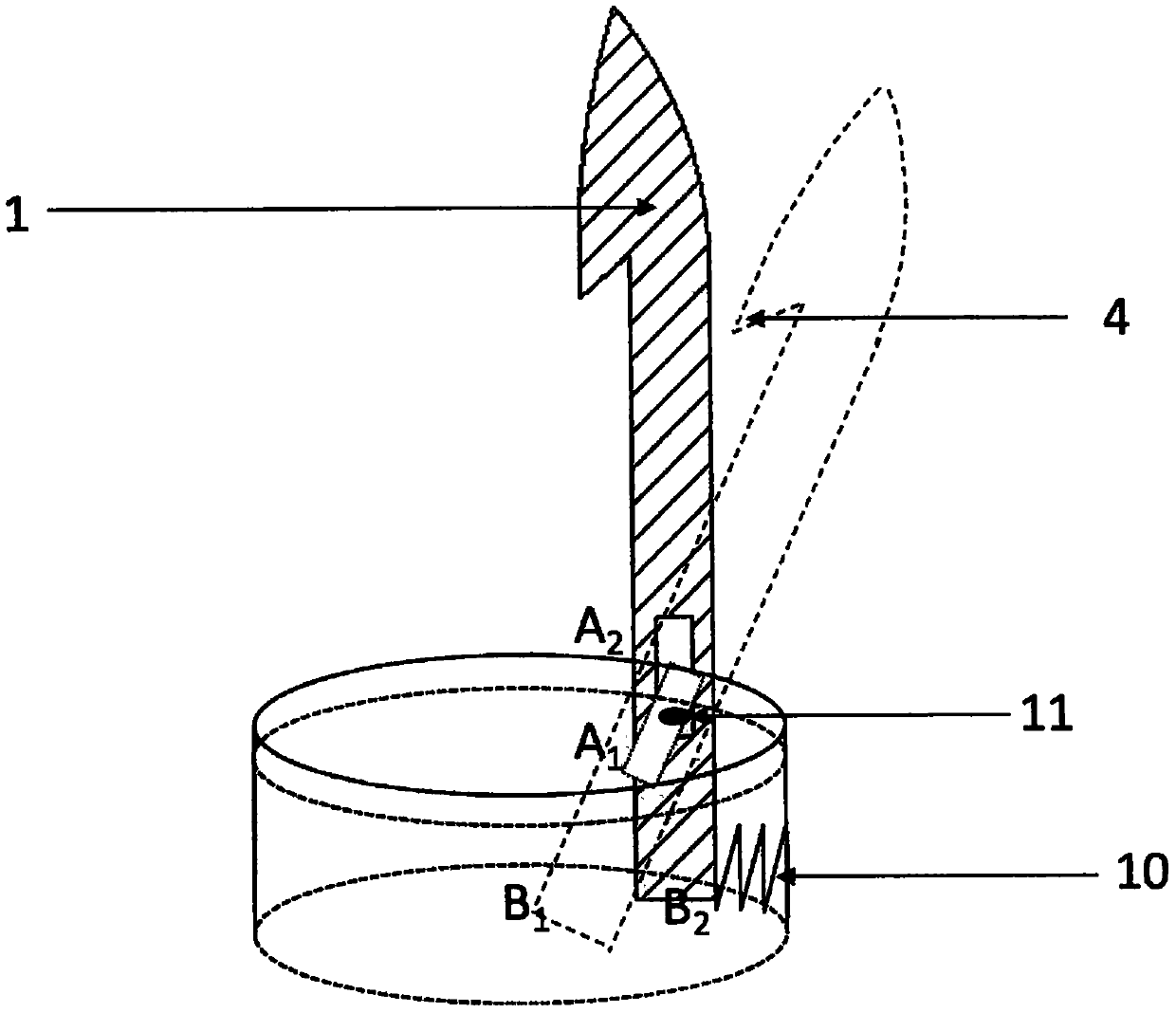
[0019] refer to figure 1 The hydraulic fishing tool of the present invention mainly includes (1) fishing claws, (2) hydraulic power unit, (3) fishing tool outer cylinder, (5) connecting thread, wherein (5) connecting thread is located at the uppermost end of the design, through (5) ) connection thread to connect the tool to the lowermost end of the drill string for fishing operations; (1) the fishing claw is the main catching tool, by passing the (11) fixed key through the (8) annular groove, the (1) fishing claw It is fixed on (3) the outer cylinder of the fishing tool, (1) the fishing claw can only rotate in the notch of (7) the outer cylinder, and the upper end of (1) the fishing claw is inside the outer cylinder of (3) the fishing tool, such as image 3 .As shown in (3) the inner wall surface of the outer cy...


PUM


Abstract

The invention relates to a hydraulic fishing tool. In the well drilling process, complicated underground accidents that a drilling tool often gets stuck often happen; especially under some complicatedgeological conditions, a part of a sleeve is severely worn in the horizontal well section of an abnormal hole, a fish falling accident and the like are caused finally, in the well completion loggingprocess, the common accident that a steel wire is broken and the like can happen. Researches shown that the common fishing tool is fixed in diameter and can only fish some underground fallen objects of a fixed size, and the function of the fishing tool has great limitation. The hydraulic fishing tool is designed to solve the problems and can fish fallen objects within a certain size range. The hydraulic fishing tool mainly comprises fishing jaws, springs, a hydraulic groove, hydraulic pushing blocks, a drilling fluid flow channel, retaining keys and the like, wherein the fishing jaws are installed on a fishing tool outer cylinder through the retaining keys. The hydraulic power provided by the drilling fluid is utilized to push the hydraulic pushing blocks to slide, sliding of the hydraulicpushing blocks drives and controls the fishing jaws to move, and then underground fallen objects are fished.

Description

technical field [0001] The invention relates to the technical field of downhole fishing tools, in particular to a hydraulic fishing tool Background technique [0002] With the continuous development of unconventional oil and gas resources, the drilling depth is getting deeper and deeper, and the well type is becoming more and more complex. There are more and more complexities in the drilling process. In some formations, the dip angle is large, the drillability is poor, and the formation In some formations with strong abrasiveness, the drill string is easy to wear and tear in some formations in the build-up section, eventually resulting in the breakage of the drilling tool and fish falling into the well; in addition, accidents of wire rope breakage sometimes occur during the electrical testing of well completion However, the salvage of the falling objects in the well is not ideal, and the falling objects are difficult to lift out, resulting in sidetracking of the injection pl...

Claims


Application Information

Patent Timeline
Patent Type & Authority Applications(China)
IPC IPC(8): E21B31/18E21B31/14E21B31/12
CPCE21B31/12E21B31/14E21B31/18
Inventor 惠城彭晓龙任威严汪海阁邹灵战卓鲁斌于璟常龙
Owner CNPC DRILLING RES INST
Learn More