
Girder reinforcing plate structure

A technology for reinforcing plates and rear floors, which is applied to superstructures, superstructure subassemblies, vehicle seats, etc., and can solve problems such as frequent loading, complicated welding relationships, and difficult operations for workers

Pending Publication Date: 2020-04-07
SAIC-GM-WULING AUTOMOBILE CO LTD
View PDF0 Cites 0 Cited by
  • Summary
  • Abstract
  • Description
  • Claims
  • Application Information

AI Technical Summary

Problems solved by technology

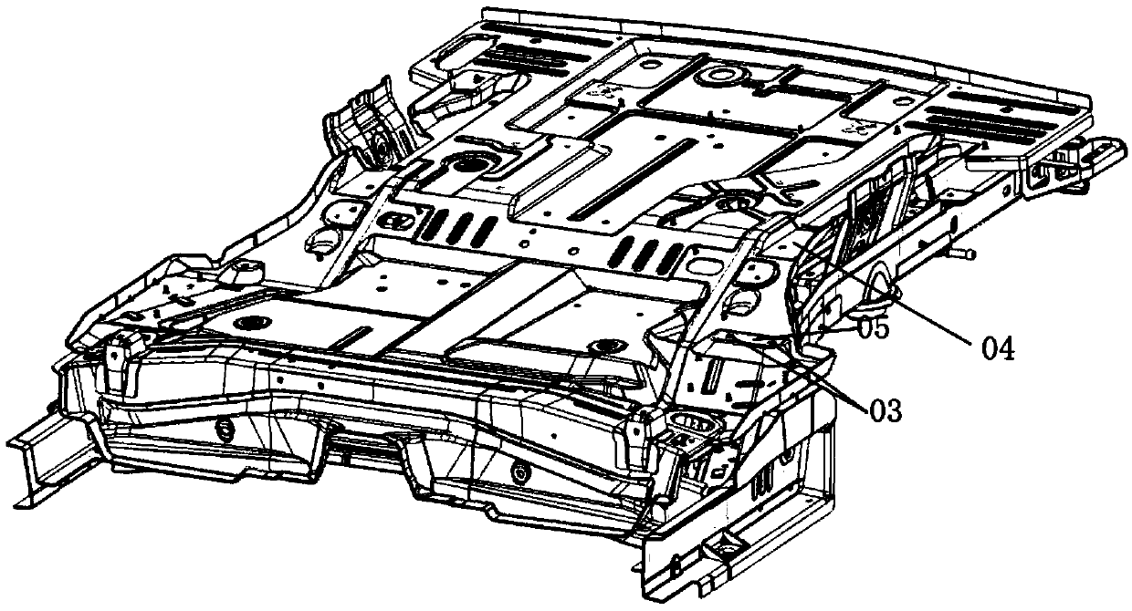
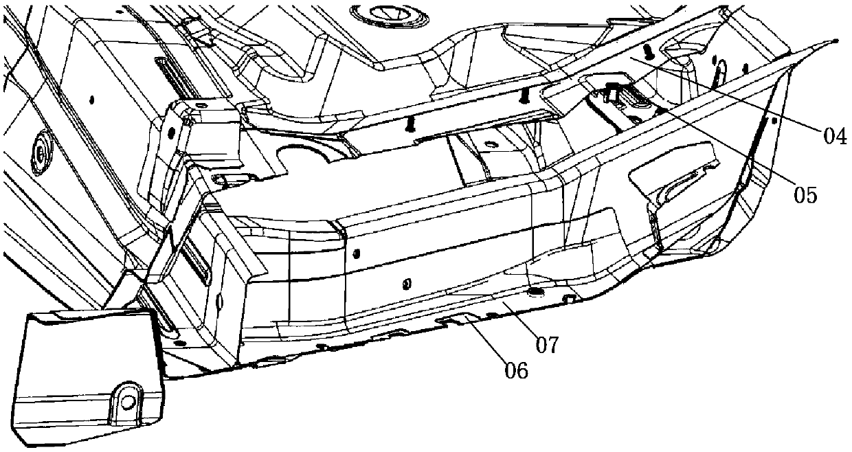
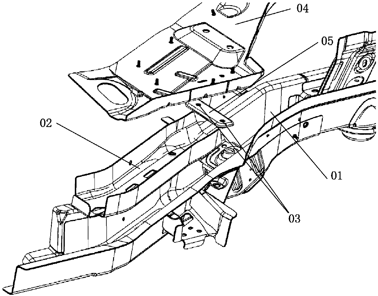
[0003] 1. The seat installation point 03 designed as an independent bracket 05 is limited by the size of the parts, and the solder joints are less, and the distribution is concentrated. support;
[0004] 2. The structure of the upper surface 06 of the rear frame assembly and the lower surface 07 of the rear frame reinforcement plate is not conducive to the entry of the electrophoretic fluid during painting. In the design, structures such as raised ribs are usually used to allow the electrophoretic fluid to enter the reinforcement plate and the frame between, but to a limited extent;
[0005] 3. The rear beam reinforcement plate 02 and the independent bracket 05 are two independent parts. There is no direct mechanical connection between the two, and the force is independent. The seat installation point 03 on the independent bracket 05 has high performance requirements. The material needs to use high-strength steel plates, and it is usually necessary to design some reinforcement structures. These reinforcement structures form a relatively complicated welding relationship with the rear frame reinforcement plate 02, and there is usually a welding sequence between the rear frame reinforcement plate 02 and the independent bracket 05. The two If there is a welding sequence between parts and other parts, the welding relationship will be very complicated, resulting in many times of loading and difficult operation for workers.

Method used


Image

  • Girder reinforcing plate structure
  • Girder reinforcing plate structure
  • Girder reinforcing plate structure

Examples


Embodiment Construction

[0029] The following with attached Figure 4 to Figure 7 A girder reinforcement plate structure of the present invention is further described in detail.

[0030] A kind of girder reinforcement plate structure of the present invention, please refer to Figure 4 to Figure 7 As shown, it includes a rear frame assembly 1, a rear frame reinforcement plate 2 and a rear floor assembly 3, the rear frame reinforcement plate 2 is located between the rear floor assembly 3 and the rear frame assembly 1, the A cavity 4 is provided between the lower surface of the front end of the rear girder reinforcement plate 2 and the upper surface of the front end of the rear girder assembly 1, the lower surface of the rear end of the rear girder reinforcement plate 2 is fixed to the upper surface of the rear girder assembly 1, The upper surface of the rear frame reinforcement plate 2 is fixed to the lower surface of the rear floor assembly 3 , and the rear seats in the car are detachably fixed on the...


PUM


Abstract

The invention discloses a girder reinforcing plate structure, which comprises a rear girder assembly, a rear girder reinforcing plate and a rear floor assembly, wherein the rear girder reinforcing plate is positioned between the rear floor assembly and the rear girder assembly; a cavity is formed between the lower surface of the front end of the rear girder reinforcing plate and the upper surfaceof the front end of the rear girder assembly; the lower surface of the rear end of the rear girder reinforcing plate is fixed to the upper surface of the rear girder assembly; the upper surface of therear girder reinforcing plate is fixed to the lower surface of the rear floor assembly; and seats in the rear row of an automobile are detachably fixed to the front end of the corresponding rear girder reinforcing plate. According to the girder reinforcing plate structure, the lower surface of the front end of the rear girder reinforcing plate is separated from the upper surface of the front endof the rear girder assembly, electrophoresis liquid can be induced to enter the space between the rear girder reinforcing plate and the rear girder assembly, the electrophoresis effect is improved, and the corrosion resistance of an automobile body is improved.

Description

technical field [0001] The invention relates to a frame reinforcement plate structure, in particular to a frame reinforcement plate structure including seat installation points in the front. Background technique [0002] Such as Figures 1 to 3 As shown, the rear frame assembly 01 is an important part of the body structure frame, and the rear frame reinforcement plate 02 is usually designed in it, and the seat installation point 03 on the body is usually designed in the cavity of the beam parts to ensure that the seat Performance of chair mounting point 03. The middle rear seat installation point 03 near the outside of the vehicle body in the existing models is usually designed as an independent bracket 05 welded on the floor assembly 04 (or rear frame assembly 01); the rear frame reinforcement plate 02 is usually designed as a U In the groove structure, the upper surface 07 of the rear frame reinforcement plate is almost completely attached to the lower surface 06 of the r...

Claims


Application Information

Patent Timeline
Patent Type & Authority Applications(China)
IPC IPC(8): B62D25/20B62D25/08B60N2/015
CPCB62D25/20B62D25/08B60N2/015
Inventor 钟靖东汪德强苟金远李书阳常光宝
Owner SAIC-GM-WULING AUTOMOBILE CO LTD
Learn More