Lower vehicle body rear frame assembly

A rear and frame technology, which is applied in the field of rear frame components of the lower body, can solve the problems of discontinuous cavity, limited force, performance defects, etc.

Pending Publication Date: 2020-04-07
SAIC-GM-WULING AUTOMOBILE CO LTD
View PDF0 Cites 2 Cited by
  • Summary
  • Abstract
  • Description
  • Claims
  • Application Information

AI Technical Summary

Problems solved by technology

[0003] 1. If figure 2 As shown, there are too few connection points between the wheel house support plate 06 and the rear frame assembly 07, and it is easy to become the weak point of the supporting frame;
[0004] 2. The positions of the crossbeam 09 and the wheel house support plate 06 are staggered, and the cavity is discontinuous;
[0005] 3. Only rely on the connection of the wheel house single plate 05 and the upper body 01, the force is limited, if it is not suitable for the load-bearing body, the whole body should be coordinated;
[0006] 3. There are too few supporting frames at the rear of the car body. For larger-sized (heavier) models, the supporting frames designed for ordinary-sized models, that is, the support of the C-pillar 010 and the middle of the lower body 02, the D-pillar 012 and the rear end plate 03 The frame has great defects in the performance requirements of the body;
[0007] 4. The support frame of the X-direction section of the existing model is usually consciously designed at the D-pillar 012 and the tailgate frame 03. The middle of the body only relies on the crossbeam 09 of the lower body 02 and the tailgate frame 03 to transmit force. When the size of the body is small, and when the body size is large, the structure has certain defects in performance, and it does not meet the principle that the load-bearing body should be coordinated by the entire body
[0008] 5. image 3 As shown, it is difficult to weld the beam lap joint 014 with the rear floor and rear frame assembly 07, especially if image 3 In the dotted line frame, when the lap joint 014 of the rear beam on the rear floor cover is welded with the rear frame assembly 07, the welding torch cannot enter the closed cavity

Method used


Image

  • Lower vehicle body rear frame assembly
  • Lower vehicle body rear frame assembly
  • Lower vehicle body rear frame assembly

Examples


Embodiment Construction

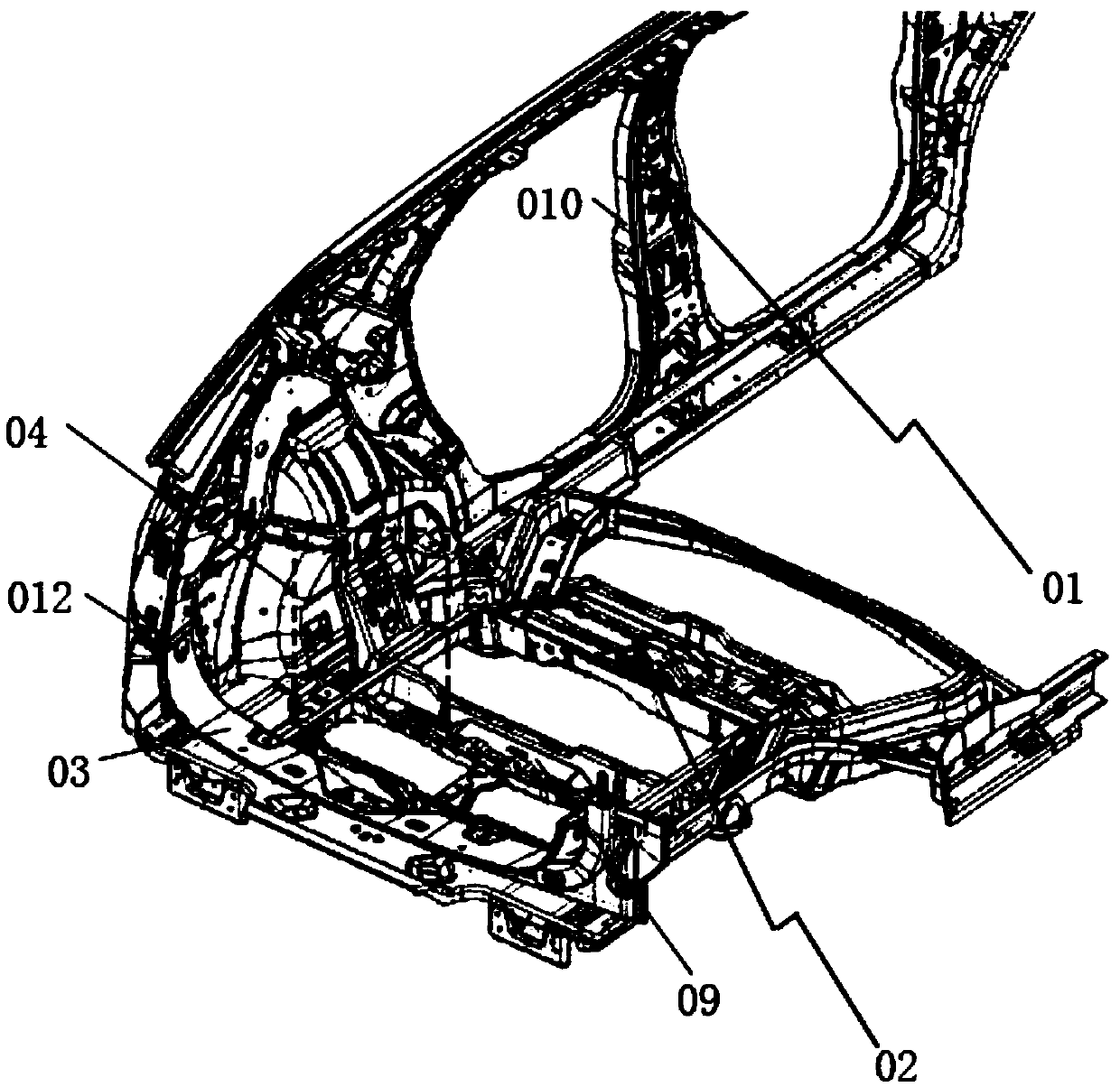
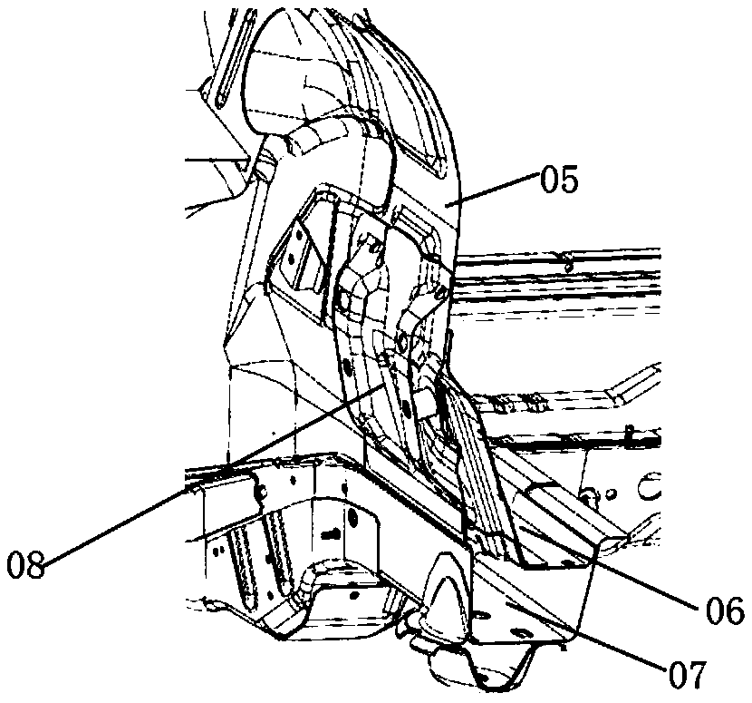
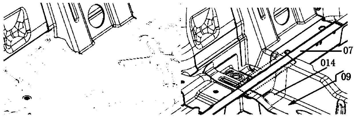
[0042] Below in conjunction with the attached drawings Figure 4 to Figure 9 A further detailed description of the rear frame assembly of the lower vehicle body of the present invention.

[0043] The rear frame assembly of the lower car body of the present invention, please refer to Figure 4 to Figure 9 As shown, it includes a wheel cover support plate 2, a rear frame partition 1, a rear frame assembly 3, the longitudinal section of the rear frame partition 1 is n-shaped, and the longitudinal section of the wheel cover support plate 2 is L-shaped. The longitudinal section of the rear frame assembly 3 is U-shaped, the rear frame partition 1 includes two first vertical walls 4 and a first horizontal wall 5, and the two first vertical walls 4 are respectively fixed on the first The left and right ends of a horizontal wall 5, the bottom walls of the two first vertical walls 4 are respectively fixedly connected with the bottom wall of the rear frame assembly 3, and the front and rea...


PUM


Abstract

The invention discloses a lower vehicle body rear frame assembly, which comprises a wheel cover supporting plate, a rear girder partition plate and a rear girder assembly. The rear girder partition plate comprises a first horizontal wall and two first vertical walls. The two first vertical walls are fixed to the left end and the right end of the first horizontal wall respectively. A partition plate cavity is formed among the two first vertical walls, the first horizontal wall, and the bottom wall and the side wall of the rear girder assembly. The wheel cover supporting plate comprises a secondhorizontal wall, a third vertical wall and two second vertical walls, the lower surface of each second horizontal wall is fixed to the upper surface of the first horizontal wall, and a supporting plate cavity is formed among the outer surface of the lower middle end of the third vertical wall, the inner surface of the the wheel cover inner plate and the outer surface of the first horizontal wall.According to the lower vehicle body rear frame assembly, on one hand, the connecting points of the wheel cover supporting plates and the rear girder assembly are increased such that the connecting strength is enhanced, and on the other hand, stress concentration at the connecting positions of the wheel cover supporting plates and the rear girder assembly is avoided.

Description

Technical field [0001] The invention relates to a rear frame assembly of a lower car body, in particular to a rear frame assembly of a lower car body with a continuous cavity structure of a car body. Background technique [0002] The support frame of the load-bearing car body is usually realized by forming a closed cavity composed of sheet metal parts in various cross-sectional directions, such as Figure 1 to Figure 2 As shown, the support frame of the X-direction cross-section of the existing vehicle is usually designed deliberately at the D-pillar 012 and the tailgate frame 03, while the middle of the body is only transmitted by the crossbeam 09 and the tailgate frame 03 of the lower body 02, and the crossbeam 09 and the wheel cover There is no continuous cavity when connecting 04 and C-pillar 010. Only the wheel cover inner plate reinforcement 08 and the wheel cover veneer form a wheel cover reinforcement plate cavity. The upper side of the wheel cover inner plate reinforcement...

Claims


Application Information

Patent Timeline
Patent Type & Authority Applications(China)
IPC IPC(8): B62D25/08B62D25/16B62D25/04B62D25/20
CPCB62D25/04B62D25/08B62D25/16B62D25/20
Inventor 钟靖东陈仁泽和丽梅李书阳常光宝
Owner SAIC-GM-WULING AUTOMOBILE CO LTD
Why Eureka
Try Eureka