Urethral catheterization structure

A urine and balloon technology, applied in the direction of catheters, balloon catheters, etc., can solve problems such as catheter irritation, urinary tract infection, bladder spasm or urinary tract irritation symptoms, so as to relieve urinary tract irritation symptoms and reduce residual , the effect of reducing the risk of urinary tract infection

Pending Publication Date: 2020-04-07
SHANGHAI XIANYI MEDICAL TECH
View PDF0 Cites 0 Cited by
  • Summary
  • Abstract
  • Description
  • Claims
  • Application Information

AI Technical Summary

Problems solved by technology

[0004] Through the structural analysis of the Foley catheter, it will be found that the above-mentioned problems are mainly caused by the structural design defect of the Foley catheter itself, mainly including the following aspects: the protruding part (ie, the guide end) of the bladder end of the catheter When the patient is empty or when the patient changes position, it is easy to poke the bladder wall of the patient, thereby inducing bladder spasm or urinary tract irritation symptoms, and repeatedly poking the bladder wall is easy to damage the epithelial protective structure of the bladder, resulting in urinary tract infection ; (2) The spherical balloon structure at the bladder end of the urinary catheter and the relative position of the drainage outlet make it possible for a small amount of urine to accumulate between the urinary catheter balloon and the bladder wall when the urinary catheter is completely emptied. stagnant water, which is also an important factor inducing urinary tract infection; (3) for short-term indwelling catheters, such as patients who need anesthesia, usually ...

Method used


Image

  • Urethral catheterization structure
  • Urethral catheterization structure
  • Urethral catheterization structure

Examples


Embodiment Construction

[0052] In order to enable those skilled in the art to better understand the technical solutions in the embodiments of the present application, the following will clearly and completely describe the technical solutions in the embodiments of the present application in conjunction with the drawings in the embodiments of the present application. Obviously, the described The embodiments are only some of the embodiments of the present application, but not all of them. All other embodiments obtained by persons of ordinary skill in the art based on the embodiments in the embodiments of the present application shall fall within the protection scope of the embodiments of the present application.

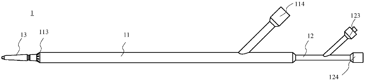
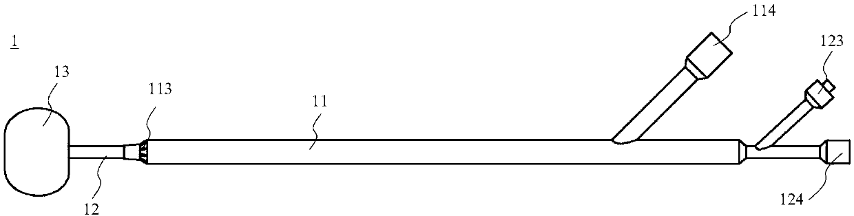
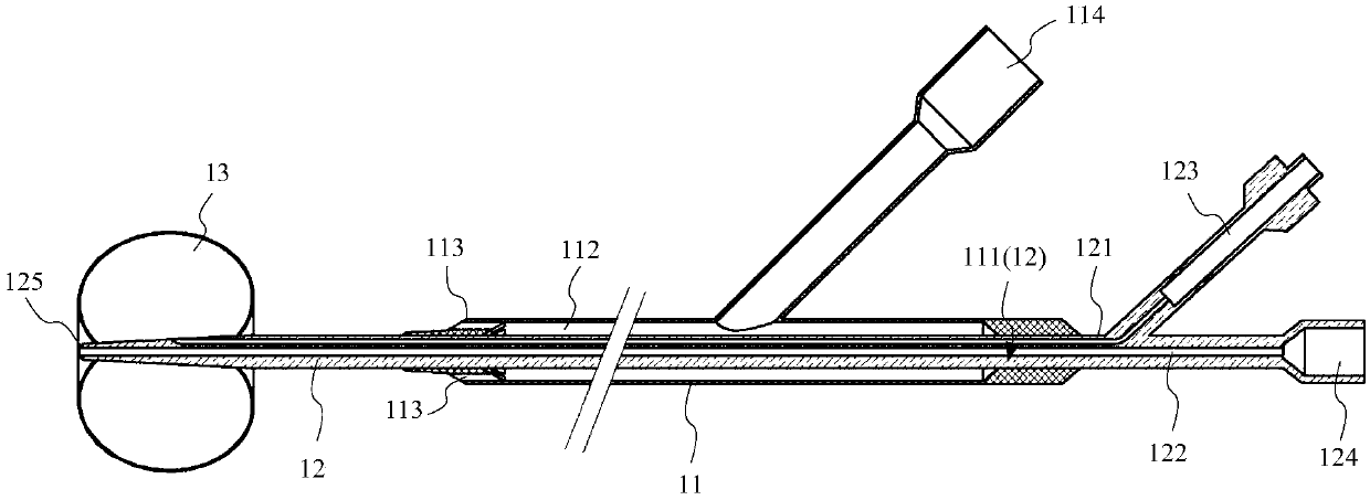
[0053] Please refer to Figure 1A to Figure 1D, which is a schematic diagram showing the overall structure of the urinary catheterization structure 1 according to an embodiment of the present application. The urinary catheterization structure 1 of the present application is arranged in the ur...


PUM


Abstract

The application provides a urethral catheterization structure. The urethral catheterization structure comprises an outer sheath pipe with a liquid discharge port, an inner core arranged in the outer sheath pipe in a penetrating manner, and a balloon arranged at a distal end of the inner core, the balloon is located in the bladder of a patient, the outer sheath pipe can receive an external force effect and conduct axial moving relative to the inner core, wherein when the liquid discharge port of the outer sheath pipe is located between the sphincter and bladder of the patient, urine in the bladder of the patient directly flows into the liquid discharge port and is also discharged out to provide a non-autonomic urination function, while when the liquid discharge port of the outer sheath pipeis located between the sphincter and external urethral orifice of the patient, urine in the bladder flows through the sphincter, enters urethra, then flows into the liquid discharge port and is discharged out via a catheterization route to provide an autonomic urination function. Therefore, the urethral catheterization structure can convert and provide functions of independent urination and non-independent urination according to actual use requirements of the patient, can effectively relieve urinary tract irritation symptoms of the patient, and reduces risks of urinary tract infection.

Description

technical field [0001] The embodiments of the present application relate to the technical field of medical devices, in particular to a catheter structure for leading out urine in the bladder. Background technique [0002] At present, the catheter widely used in clinical medicine is the Foley catheter invented in the 1930s. Compared with the previous catheters, this type of catheter has the advantages of softness, elasticity, easy fixing, and waterproof, so it is still in use today. However, the current Foley catheter also has obvious defects, and the complications caused by these defects are also widespread in clinical practice. [0003] For example, in the United States in 2002, the number of visits to doctors simply because of the problem of Foley catheters was as high as 7 million, and the direct and indirect losses were as high as 1.6 billion US dollars. In addition, there were many incalculable pains caused to patients. These complications include catheter-related urin...

Claims


Application Information

Patent Timeline
IPC IPC(8): A61M25/10
CPCA61M25/0017A61M25/0021A61M25/0043A61M25/1002A61M25/10184A61M2025/006A61M2025/1086A61M25/10
Inventor 高翔
Owner SHANGHAI XIANYI MEDICAL TECH
Why Eureka
Try Eureka