Assembled power distribution cabinet

A power distribution cabinet and assembled technology, which is applied in substation/power distribution device housing, electrical components, substation/switch layout details, etc., can solve the problems of difficult to ensure the personal safety of staff, difficulties in dust removal or maintenance process, and large side panels and other problems, to achieve the effect of convenient manufacturing and transportation, convenient modular installation, and increased operating space

Inactive Publication Date: 2020-04-03
郑州联开电气设备有限公司
View PDF5 Cites 6 Cited by
  • Summary
  • Abstract
  • Description
  • Claims
  • Application Information

AI Technical Summary

Problems solved by technology

[0003] When the power distribution cabinet is manufactured, the angle steel or steel plate is usually welded into a square steel frame first, then the cabinet door is installed on one side of the steel frame, and finally the side panels are installed on the other three sides of the steel frame. The side panels are usually passed through The bolts are connected to the steel frame, the side panels are large in size, and it is very laborious to install, and the three side panels need to be installed one by one, which is a waste of time; and the inside of the power distribution cabinet needs to be dusted or repaired during long-term use, while the side panels need to be installed one by one, which is a waste of time; The board is fixed on the steel frame, and the staff can only open the cabinet door and lean into the cabinet for inspection during dust removal or maintenance. The process of dust removal or maintenance is difficult, and it is difficult to ensure the personal safety of the staff.

Method used


Image

  • Assembled power distribution cabinet
  • Assembled power distribution cabinet
  • Assembled power distribution cabinet

Examples


Embodiment Construction

[0043] The present invention will be described in further detail below in conjunction with the accompanying drawings.

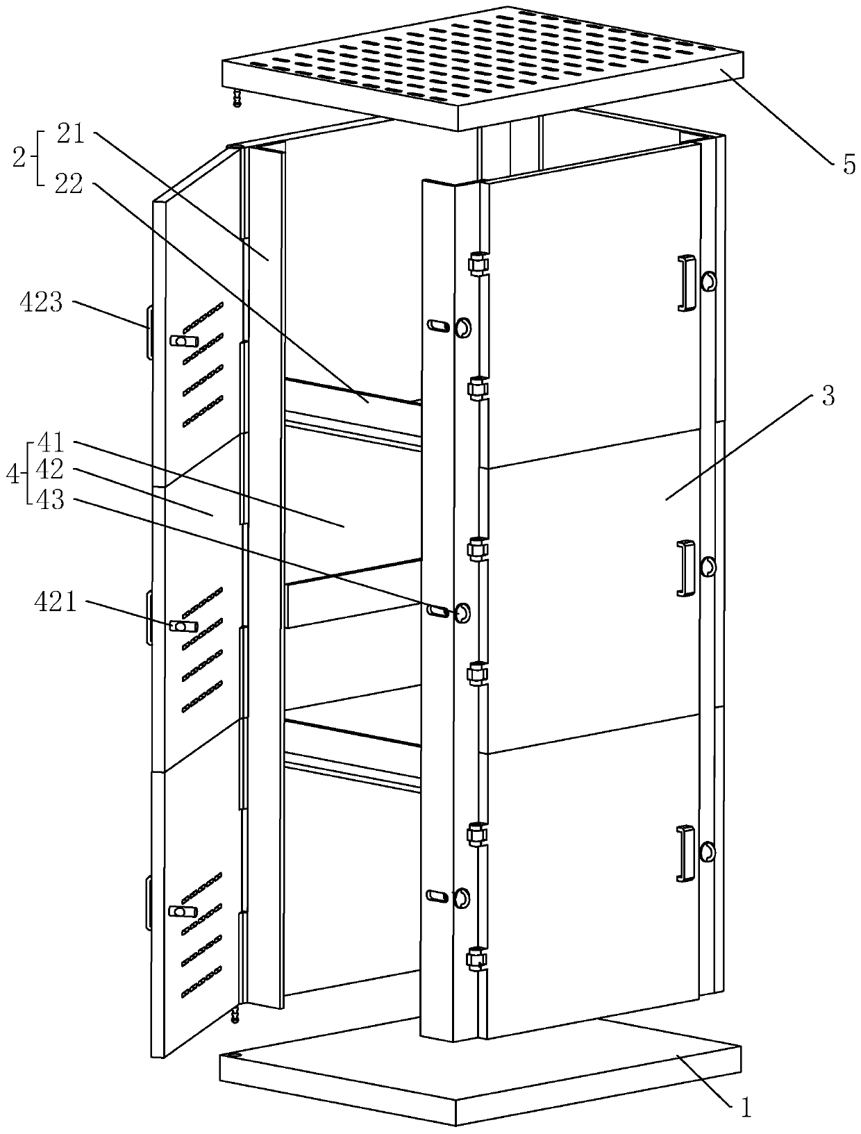
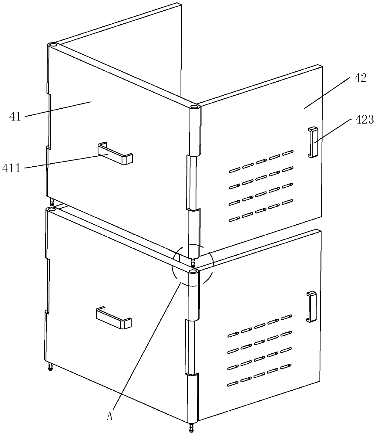
[0044] refer to figure 1 with figure 2 , is a combined power distribution cabinet disclosed in the embodiment of the present invention, including a bottom plate 1, a steel frame 2, a cabinet door 3, several assembly units 4 and a top plate 5, and the steel frame 2 includes four vertical and fixedly connected to the bottom plate 1. A vertical angle steel 21 and a plurality of horizontal angle steels 22 fixedly connected between adjacent vertical angle steels 21, four vertical angle steels 21 surround and form a square area, and the horizontal angle steels 22 are used for installing and carrying electrical components; the cabinet door 3 Hinged between two vertical angles 21; each group of assembled units 4 includes a first side plate 41 opposite to the cabinet door 3, and a second side plate 42 hinged on the opposite sides of the first side plate 41 And the ...


PUM


Abstract

The invention discloses an assembled power distribution cabinet, and relates to the technical field of power distribution cabinets. The assembled power distribution cabinet comprises a bottom plate, asteel frame arranged on the bottom plate, a cabinet door hinged to one side surface of the steel frame, a plurality of assembly units vertically and upwards arranged in sequence along the upper surface of the bottom plate, and a top plate covering the top of the steel frame, the steel frame comprises vertical angle steel perpendicularly connected to the bottom plate and a plurality of horizontalangle steel fixedly connected between the adjacent vertical angle steel. Each assembly unit comprises a first side plate arranged on the side opposite to the cabinet door, second side plates hinged tothe two opposite side edges of the first side plate respectively, and locking assemblies arranged between the second side plates and the vertical angle steel. Inserting rods are arranged at the two ends of the lower end faces of the first side plates respectively, inserting grooves are formed in the two ends of the upper end faces of the first side plates respectively, and the splicing units aresequentially connected end to end in an inserted mode. The assembled power distribution cabinet has the effect of being convenient to install and overhaul.

Description

technical field [0001] The invention relates to the technical field of power distribution cabinets, in particular to an assembled power distribution cabinet. Background technique [0002] Power distribution cabinets are divided into power distribution cabinets and lighting distribution cabinets. They are the final equipment of the power distribution system and are collectively referred to as motor control centers. The power distribution cabinet is used in the occasions where the load is relatively scattered and there are few circuits; the motor control center is used in the occasions where the load is concentrated and there are many circuits. They distribute the electric energy of a certain circuit of the upper-level power distribution equipment to the nearest load. This level of equipment shall provide protection, monitoring and control of the load. [0003] When the power distribution cabinet is manufactured, the angle steel or steel plate is usually welded into a square...

Claims


Application Information

Patent Timeline
Patent Type & Authority Applications(China)
IPC IPC(8): H02B1/30
CPCH02B1/301
Inventor 石麦会尚静卫肖云飞王永胜
Owner 郑州联开电气设备有限公司
Why Eureka
Try Eureka