Material carrying anti-collision device
An anti-collision device and material technology, applied in the direction of low internal friction spring, spring/shock absorber, vibration suppression adjustment, etc., can solve the problems that the handling device has no anti-collision structure, the handling device is easily damaged, and affects the production progress, etc., to achieve Improve the protective measures, improve the anti-collision ability, and reduce the effect of frontal impact force
- Summary
- Abstract
- Description
- Claims
- Application Information
AI Technical Summary
Problems solved by technology
Method used
Image


Examples
Embodiment 1
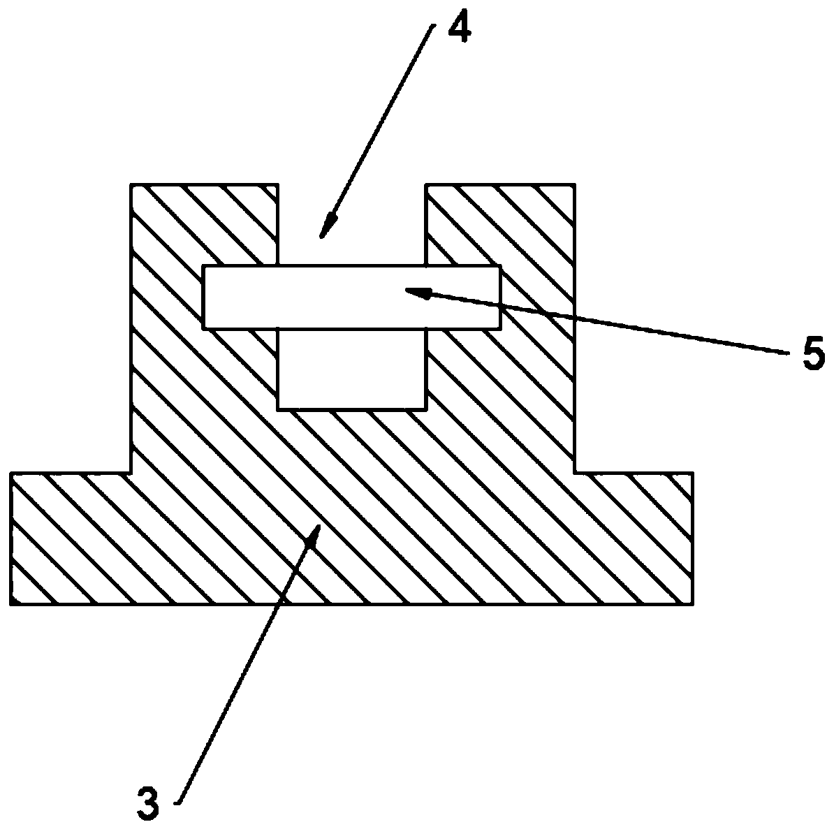
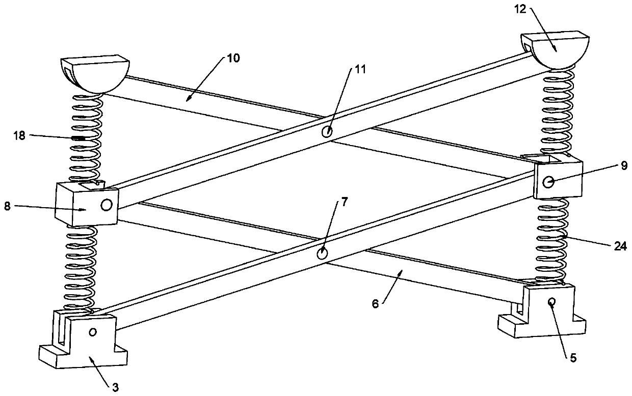
[0020] see Figure 1~3 , in an embodiment of the present invention, a material handling anti-collision device includes a mounting frame 1, a chute-2 is arranged on the mounting frame 1, and a slider-3 is slidably installed at both ends of the chute-2, and the slider A groove 4 is provided on the groove 4, and a fixed column 5 is arranged in the groove 4, and the two ends of the fixed column 5 are fixedly connected on the inner side wall of the groove 4, and a connecting rod 6 is installed on the fixed column 5, and the connecting rod The middle part of one 6 is provided with hinge column one 7, and the left and right two described connecting rods one 6 are hinged by hinge column one 7, and the end of described connecting rod one 6 is provided with concave block 8, and hinge column two 9 is arranged in the concave block 8, hinged The second column 9 is hinged with a connecting rod 2 10, and the middle of the connecting rod 10 is provided with a hinged column 3 11, the two conne...
Embodiment 2
[0024] In order to prevent spring 3 22 from being damaged due to a large inclination caused by external force, this embodiment is further improved on the basis of embodiment 1. The improvement is: the side walls at both ends of the support plate 14 are fixedly connected with spring 4 23. The end of spring four 23 is fixedly connected to the inner wall of the protective shell 19. When the protective shell 19 is hit by a foreign object, the spring four 23 can prevent the protective shell 19 from tilting greatly, and prevent the spring three 22 from being damaged beyond its bearing range The material of the spring four 23 is not limited, in this embodiment, preferably, the material of the spring four 23 is alloy spring steel.
[0025] The working principle of this embodiment is: when the protective shell 22 is subjected to a relatively large impact, the protective shell 22 will deviate, causing the spring three 22 to bend, and when the spring three 22 bends beyond its bearing rang...
Embodiment 3
[0027] In order to further increase the anti-collision capability of the device, this embodiment is further improved on the basis of Embodiment 1. The improvement is: a spring two 18 is arranged between the fixed seat 12 and the concave block 8, and one end of the spring two 18 Fixedly connected to the bottom of the fixed seat 12, the other end is fixedly connected to the top of the concave block 8, a spring five 24 is arranged between the concave block 8 and the slider one 3, and one end of the spring five 24 is fixedly connected to the bottom of the concave block 8. The bottom end and the other end are fixedly connected to the top of slider one 3. When the support plate 14 is hit and moves downward, spring two 18 and spring five 24 can play an effective buffer role, further improving the anti-collision ability of the device .
[0028] The working principle of this embodiment is: a spring two 18 is set between the fixed seat 12 and the concave block 8, and a spring five 24 is...
PUM
 Abstract
Description
Claims
Application Information
 - R&D
- Intellectual Property
- Life Sciences
- Materials
- Tech Scout
- Unparalleled Data Quality
- Higher Quality Content
- 60% Fewer Hallucinations
Browse by: Latest US Patents, China's latest patents, Technical Efficacy Thesaurus, Application Domain, Technology Topic, Popular Technical Reports.
© 2025 PatSnap. All rights reserved.Legal|Privacy policy|Modern Slavery Act Transparency Statement|Sitemap|About US| Contact US: help@patsnap.com