
Novel vertical-axis wind driven generator and assembly method thereof

A technology of wind power generators and assembly methods, which is applied to the combination of wind power generators, the assembly of wind power engines, wind power engines, etc., and can solve the problems of difficult assembly of wind power generators, time-consuming and labor-intensive repairs and maintenance, etc.

Pending Publication Date: 2020-04-03
无锡风腾新能源科技发展有限公司
View PDF0 Cites 0 Cited by
  • Summary
  • Abstract
  • Description
  • Claims
  • Application Information

AI Technical Summary

Problems solved by technology

[0007] The invention provides a new type of vertical axis wind generator and its assembly method, which solves the problems of difficult assembly of current wind generators and time-consuming and labor-intensive repair and maintenance.

Method used


Image

  • Novel vertical-axis wind driven generator and assembly method thereof
  • Novel vertical-axis wind driven generator and assembly method thereof

Examples


Embodiment 1

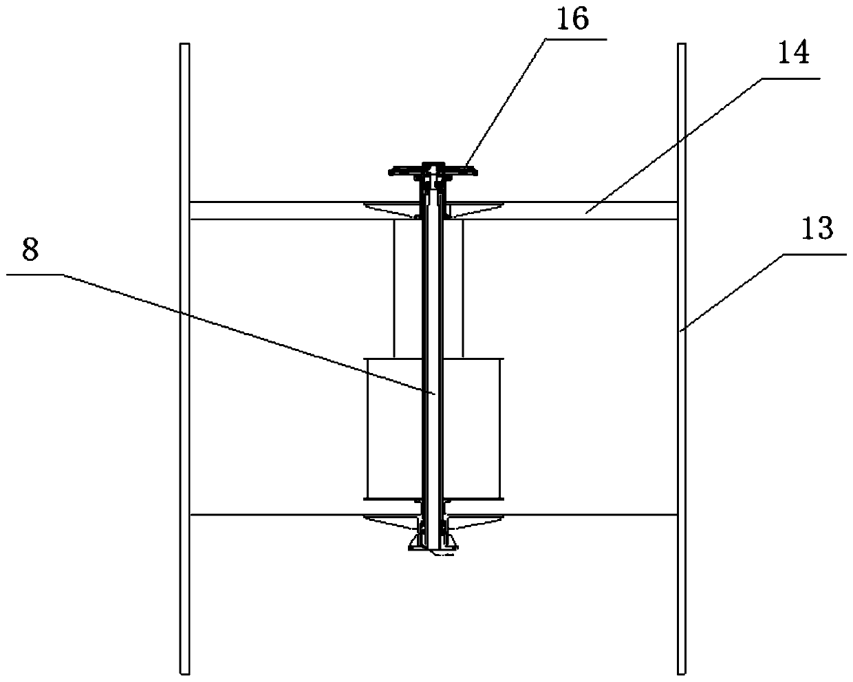
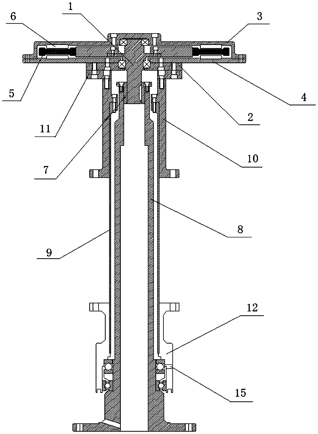
[0032] Such as figure 1 and figure 2 As shown, a novel vertical axis wind power generator includes a magnetic levitation generator assembly 16, the motor shaft 1 of the magnetic levitation generator assembly 16 is connected to the fan shaft 8 through the motor shaft adapter sleeve 7, and the fan shaft 8 is rotatably fitted with a fan barrel 9, the upper end of the fan barrel 9 is equipped with a bracket upper support sleeve 10, the lower end of the fan barrel 9 is equipped with a bracket lower support sleeve 12, and the support upper support sleeve 10 passes through the The connecting flange 11 is connected with the motor bearing cover 2 below the magnetic levitation generator assembly 16 , and the fan blade 13 is installed on the upper support sleeve 10 and the lower support sleeve 12 of the support through the support 14 .

[0033] During use, fan blade 13 is driven by the wind force, drives blower cylinder body 9 through support 14 and the shell of magnetic levitation gen...

Embodiment 2

[0039] A method for assembling a novel vertical axis wind power generator, comprising the steps of:

[0040] (1) Place the main shaft of the fan 8 vertically, support the sleeve 12 and the barrel of the fan 9 under the set bracket;

[0041] (2) Fan blade 13 is installed on the support 14;

[0042] (3) Continue to install the upper support sleeve 10 on the fan barrel 9;

[0043] (4) Install the support 14 with the fan blade 13 installed on the upper support sleeve 10 of the support and the lower support sleeve 12 of the support;

[0044] (5) Install the motor shaft adapter sleeve 7 on the fan shaft 8;

[0045] (6) Install the connecting flange 11 on the support sleeve 10 on the bracket;

[0046] (7) Finally, put the magnetic levitation generator assembly 16 into it.

[0047] Before the actual assembly, each part can be cleaned with diesel oil, which can remove impurities on the surface of the parts and play a good role in lubrication, which is convenient for subsequent asse...


PUM


Abstract

The invention discloses a novel vertical-axis wind driven generator and an assembly method thereof and relates to the field of wind driven generators. The wind driven generator comprises a magnetic suspension generator assembly. A motor spindle of the magnetic suspension generator assembly is connected with a fan spindle through a motor spindle reducing sleeve, a fan cylinder rotatably sleeves thefan spindle, and the upper end of the fan cylinder is provided with a support upper supporting sleeve. The lower end of the fan cylinder is provided with a support lower supporting sleeve, the support upper supporting sleeve is connected with a motor bearing cover below the magnetic suspension generator assembly through a connection flange, and a fan blade is installed on the support upper supporting sleeve and the support lower supporting sleeve through a support. According to the novel vertical-axis wind driven generator, by adopting upper-arrangement design for the magnetic suspension generator assembly, the magnetic suspension generator assembly is installed on the top end of the wind driven generator, and when the magnetic suspension generator assembly is overhauled or replaced, themagnetic suspension generator assembly of the upper portion only needs to be opened and detached.

Description

technical field [0001] The invention relates to the field of wind power generators, in particular to a novel vertical axis wind power generator and an assembly method thereof. Background technique [0002] At present, in the traditional vertical-axis wind turbines on the market, the generator part is arranged at the lower position of the whole wind turbine. The disadvantages of wind turbines assembled in this way are: [0003] 1. The assembly of the whole machine is difficult. Conventional vertical-axis wind turbines must be assembled step by step from bottom to top. Any step of assembly with low accuracy will cause rework and consume a lot of manpower and material resources. [0004] 2. The cost of packaging and transportation is high. When the conventional vertical axis wind turbine is shipped and packaged, because the host part cannot be disassembled, it can only be packaged as a whole, resulting in a large volume and heavy weight of the box, especially when it is tran...

Claims


Application Information

Patent Timeline
IPC IPC(8): F03D9/25F03D3/00F03D13/10
CPCF03D9/25F03D3/005F03D13/10Y02E10/74
Inventor 张长强
Owner 无锡风腾新能源科技发展有限公司
Learn More