
Light-emitting-area-adjustable lamp

A technology of light-emitting area and lamps, which is applied in the field of plant lighting, can solve the problems of reducing storage, transportation and packaging costs, fixed light-emitting area, and large volume of lamps, and achieves the advantages of reduced packaging and transportation costs, convenient operation and use, and large light-emitting area. Effect

Pending Publication Date: 2021-12-07
PLUSRITE ELECTRIC CHINA +1
View PDF0 Cites 0 Cited by
  • Summary
  • Abstract
  • Description
  • Claims
  • Application Information

AI Technical Summary

Problems solved by technology

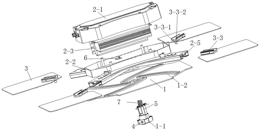
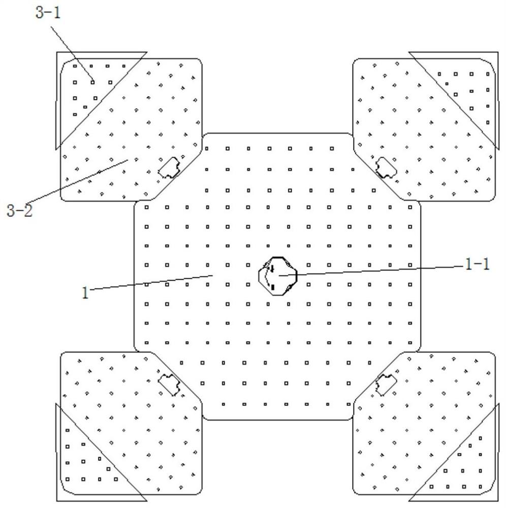
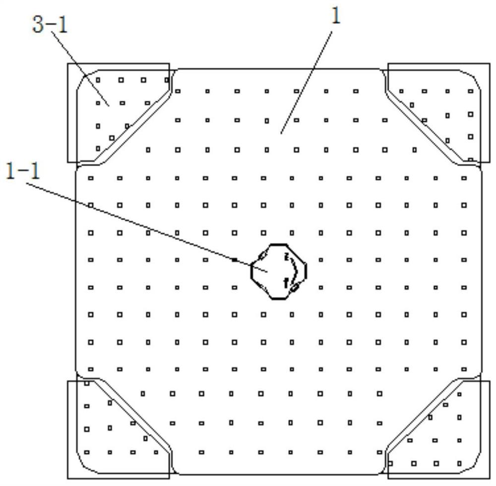
[0003] The invention solves the problems of large volume, high logistics cost and fixed luminous area in the related art, which cannot be adjusted according to the use requirements, and proposes a luminaire with adjustable luminous area. Expand and shrink along the radial direction of the central lamp body. In the contracted state, the light-emitting area is a small part of the entire central lamp body plus the side lamp body. When unfolded, the light-emitting area is the entire center lamp body plus the side lamp body. The area is easy to adjust; the side lamp body shrinks during packaging and transportation, the structure is compact, and the volume is only 40% of the fully expanded volume, which reduces storage, transportation and packaging costs; when in use, you can flexibly choose the lamp by controlling the state of the side lamp body Power and light-emitting area size, no external wiring, ready to use, no wiring, beautiful and easy to use

Method used


Image

  • Light-emitting-area-adjustable lamp
  • Light-emitting-area-adjustable lamp
  • Light-emitting-area-adjustable lamp

Examples


Embodiment Construction

[0029] The following will clearly and completely describe the technical solutions in the embodiments of the present invention with reference to the accompanying drawings in the embodiments of the present invention. Obviously, the described embodiments are only some, not all, embodiments of the present invention. The following description of at least one exemplary embodiment is merely illustrative in nature and in no way taken as limiting the invention, its application or uses. Based on the embodiments of the present invention, all other embodiments obtained by persons of ordinary skill in the art without creative efforts fall within the protection scope of the present invention.

[0030] It should be noted that the terminology used here is only for describing specific implementations, and is not intended to limit the exemplary implementations according to the present application. As used herein, unless the context clearly dictates otherwise, the singular is intended to include...


PUM


Abstract

The invention relates to the technical field of plant lighting, in particular to a light-emitting-area-adjustable lamp which comprises a center lamp body, a power source box body, side wing lamp bodies and a rotating shaft, and a rotating handle is installed on the center lamp body; a power source and a control circuit board are installed in the power source box body, a sensor is installed on the control circuit board, and the power source is electrically connected with the sensor, the center lamp body and the side wing lamp bodies; the side wing lamp bodies are installed on the power source box body in a sliding mode so as to achieve expansion and contraction; and the rotating shaft is connected with the rotating handle, can freely slide in the axial direction and can shield the sensor. The side wing lamp body shrinks during packaging and transportation, the structure is compact, and the storage, transportation and packaging cost is reduced; during use, the power and the light-emitting area of the lamp can be flexibly selected by controlling the state of the side wing lamp body, no visible wiring exists outside, the lamp can be used after being electrified, wiring is not needed, and the lamp is attractive, elegant and convenient to use.

Description

technical field [0001] The invention relates to the technical field of plant lighting, in particular to a lamp with an adjustable luminous area. Background technique [0002] Increasing the yield of crops through artificial light supplementation and shortening the growth cycle has been widely used in crop planting in recent years, and it has become an explosive growth trend. Plant growth requires a certain optical density and uniformity. In order to obtain higher yields, supplementary light is required. High-quality lamps can provide a large range of illumination, light intensity and uniformity of light distribution, which lead to the size of the lamps needing to be large enough to meet the requirements of light intensity and illumination range required for plant growth. At the same time, with the rapid development of the Internet and the logistics industry, the proportion of online sales through the Internet is constantly rising. Online sales involve a large proportion of ...

Claims


Application Information

Patent Timeline
IPC IPC(8): F21S9/02F21V19/02F21V14/02F21V23/00A01G7/04
CPCF21S9/02F21V19/02F21V14/02F21V23/006A01G7/045
Inventor 吴劲松孙志前洪世豪刘凯钱松
Owner PLUSRITE ELECTRIC CHINA
Learn More