
Suspended self-support type piling method and piling machine

A self-supporting, piling machine technology, applied in the direction of sheet pile walls, buildings, infrastructure engineering, etc., can solve the problem that the bridge erecting machine cannot guarantee to provide a stable support position, cannot complete the piling operation of heavy prefabricated piles, travel and load limitations, etc. problems, achieve the effect of lifting stroke and load, saving construction cost and convenient operation

Pending Publication Date: 2020-04-03
GUANGDONG LIYUAN HYDRAULIC MACHINERY
View PDF1 Cites 9 Cited by
  • Summary
  • Abstract
  • Description
  • Claims
  • Application Information

AI Technical Summary

Problems solved by technology

This invention still has deficiencies. The construction method of this invention needs to continuously provide a stable support position at the front end of the bridge erecting machine for supporting the longitudinal support frame extending to the ground, and it still cannot be suspended in the air, especially in the construction of rivers, seas and lakes. , the front end of the bridge erecting machine cannot guarantee to provide a stable support position at all, resulting in difficulties in construction
[0004] At the same time, most of the power units such as the telescopic arm of the existing suspended pile driver use hydraulic equipment, and their travel and load are greatly restricted, and it is impossible to complete the piling operation of heavy-duty, super-long (100 meters and above) prefabricated piles

Method used


Image

  • Suspended self-support type piling method and piling machine
  • Suspended self-support type piling method and piling machine
  • Suspended self-support type piling method and piling machine

Examples


Embodiment 1

[0075] Embodiment 1: The suspended self-supporting piling method provided by this embodiment comprises the following steps:

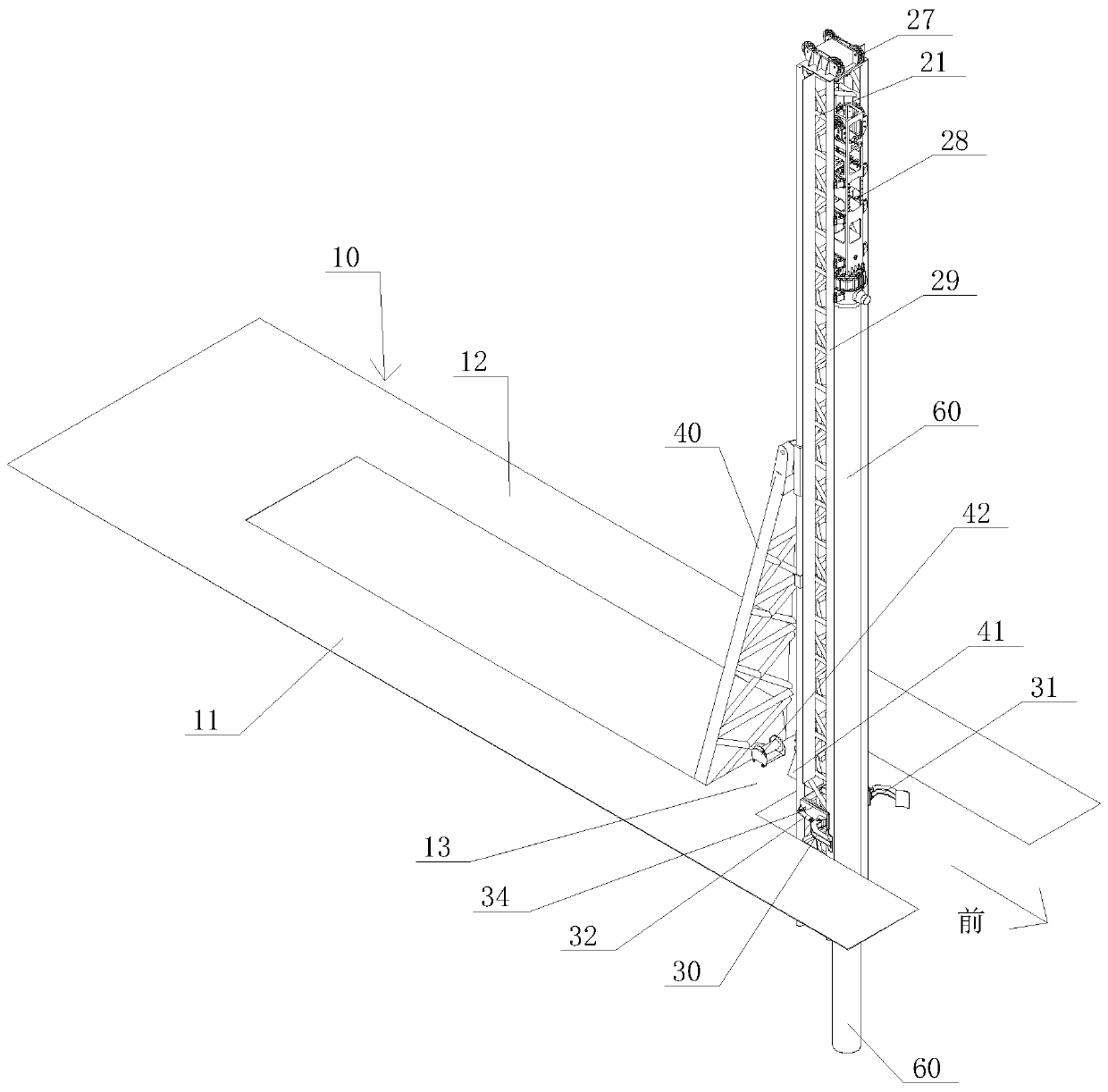
[0076] (1), the first girder 11 and the second girder 12 of the bridge erecting mechanism 10 are stretched forward, so that the front end support link beam 13 of the bridge erecting mechanism 10 is suspended above the pile foundation to be constructed;

[0077] (2), utilize bridging mechanism 10 to be installed prefabricated pile 60 horizontally on the front side of piling mechanism 20 column pylons 21, and the prefabricated pile 60 to be constructed is fixed with column pylon 21;

[0078] (3), start the luffing hoist 42, tighten the luffing wire rope 421 of the luffing hoist 42, shorten the distance between the first pulley 471 and the second pulley 472 of the luffing pulley group 47, and change the support frame 45 and bridging accordingly The triangular dimensional relationship between the mechanism 10 and the column tower 21 realizes the variable am...

Embodiment 2

[0090] The suspended self-supporting piling method provided by this embodiment is basically the same as that of Embodiment 1, except that:

[0091] Described step 1 (before step 2) also comprises the following steps:

[0092] The prefabricated pile 60 to be constructed is transported to the second half of the bridge erecting mechanism 10, and is located between the first main girder 11 and the second main girder 12, wherein the bridge erecting mechanism 10 includes the first half and the rear half, and the piling mechanism 20 is located at first half;

[0093] Start the first crane crane 151 and the second crane crane 152, and the front end and rear end of the prefabricated pile 60 to be constructed are hoisted on the first crane crane 151 and the second crane crane 152 respectively;

[0094] Simultaneously move the first lifting crane 151 and the second lifting crane 152, and move the first lifting crane 151 and the second lifting crane 152 to the first half of the bridging ...

Embodiment 3

[0098] The suspended self-supporting piling method provided by this embodiment is basically the same as that of Embodiment 1 and 2, except that:

[0099] Installing the prefabricated pile 60 to be constructed on the column tower 21 of the piling mechanism 20 also includes the following steps:

[0100] When the prefabricated pile 60 to be constructed is placed on the front side of the column tower 21, the first clamping oil cylinder 32 and the second clamping oil cylinder 33 are started, and the first clamping oil cylinder 32 and the second clamping oil cylinder 33 are extended to drive The first clamping arm 30 and the second clamping arm 31 clamp the prefabricated pile 60 to be constructed, and clamp and fix the prefabricated pile 60 to be constructed and the front side of the column tower 21 .

[0101] A suspended self-supporting pile driver implementing the above piling method, which includes a bridging mechanism 10, a piling mechanism 20, a folding mechanism 40, and the fo...


PUM


Abstract

The invention discloses a suspended self-support type piling method and a piling machine. The suspended self-support type piling method comprises the following steps: forwards extending a first main beam and a second main beam, and suspending a front-end supporting joining beam above a to-be-constructed pile foundation; horizontally mounting the to-be-constructed precast pile on the front side surface of a stand column tower frame, and fixing the to-be-constructed precast pile; starting an amplitude-varying winch, shortening a distance between a first slide wheel and a second slide wheel, realizing amplitude varying of the stand column tower frame; while amplitude varying of the stand column tower frame achieves a predetermined amplitude-varying angle, extending an amplitude-varying telescopic oil cylinder, and rotatably connecting a second slide support base with an amplitude-varying oil cylinder fixing base through a movable insertion pin; and shrinking the amplitude-varying telescopic oil cylinder, and lifting the stand column tower frame to a predetermined angle which corresponds to the to-be-constructed pile foundation. The key point of the suspended self-support type piling method is that the original bridging mechanism is utilized to perform collaborative design of the process and equipment for suspended piling for a heavy ultra-long precast pile, structure collaborativedesign of a bridging machine and the piling machine is also performed, a supporting position at the front end does not need to provide, the construction cost is reduced, and progress of works is improved.

Description

technical field [0001] The invention relates to the field of pile foundation construction, in particular to a suspended self-supporting pile driving method and a pile driver. Background technique [0002] The superstructure construction of existing highways, railways, pipelines and other viaducts is increasingly being prefabricated in factories and then transported to the site for assembly. This method requires the lower pile foundation to be laid in advance, and the pile foundation needs to be constructed in advance with an independent construction plan. If the engineering geological conditions are complex or in rivers, seas and lakes, the construction of pile foundations will be difficult and the progress of the project will be slow, and the cost of additional facilities such as piling boats and temporary trestles will be high. [0003] In the prior art, the Chinese invention patent with application number 201811007101.6 discloses a piling method and special equipment usi...

Claims


Application Information

Patent Timeline
IPC IPC(8): E02D7/06
CPCE02D7/06
Inventor 冯欣华庞国达欧天全杨树金
Owner GUANGDONG LIYUAN HYDRAULIC MACHINERY
Learn More