
A kind of nylon tube automatic heating forming equipment and forming process

一种自动加热、成型设备的技术,应用在尼龙管成型领域,能够解决易发生缓慢伸展、温度降低、弯管精度下降等问题,达到保证成型质量、防止转动和扭曲、加工效率高的效果

Active Publication Date: 2021-07-30
ZHEJIANG BOSHITE MECHANICAL CO LTD
View PDF7 Cites 0 Cited by
  • Summary
  • Abstract
  • Description
  • Claims
  • Application Information

AI Technical Summary

Problems solved by technology

[0005] However, when the above-mentioned equipment is in use, the nylon tube cannot be heated during the process from the heating assembly to the outer bending wheel assembly, so that the temperature of the nylon tube decreases when it reaches the bending wheel assembly, and then the nylon tube is bent by the bending wheel assembly. After setting the angle and radian, it is prone to slow stretching, which reduces the precision of the pipe bending

Method used


Image

  • A kind of nylon tube automatic heating forming equipment and forming process
  • A kind of nylon tube automatic heating forming equipment and forming process
  • A kind of nylon tube automatic heating forming equipment and forming process

Examples


Embodiment 1

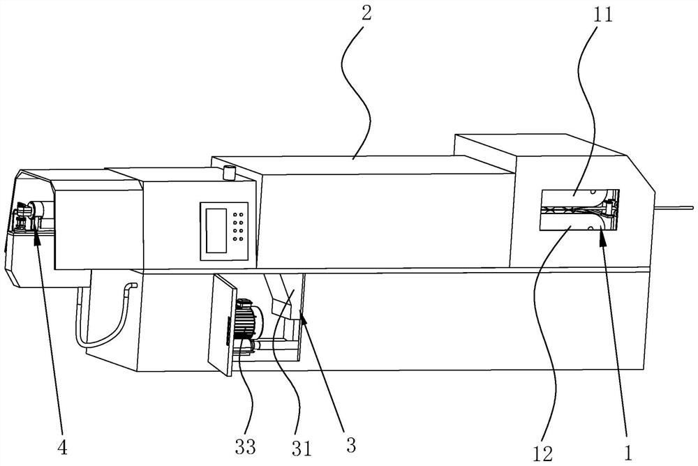
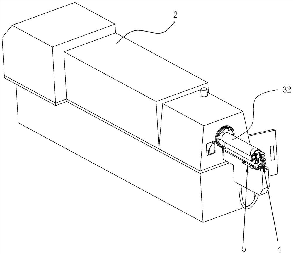
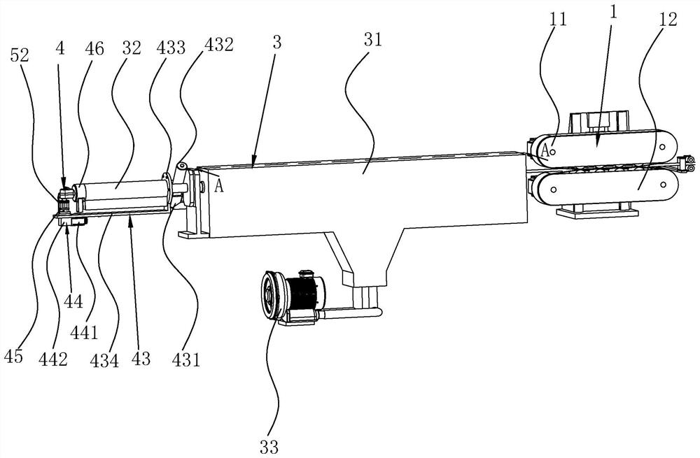
[0056] refer to figure 1 , figure 2 , image 3 , is an automatic heating and forming equipment for nylon tubes disclosed in the present invention, comprising a fuselage 2, a feeding assembly 1, a heating assembly 3 and a pipe bending assembly 4 sequentially arranged in the fuselage 2, and the heating assembly 3 includes and The oven 31 connected to the feeding assembly 1 and the electric heating cylinder 32 arranged between the oven 31 and the elbow assembly 4, the electric heating cylinder 32 is provided with a heating ring, and the nylon tube is fed from the feeding assembly 1 and passed through the oven 31 and the electric heating cylinder 32 and enter the elbow assembly 4, the electric heating cylinder 32 and the elbow assembly 4 are arranged outside the fuselage 2, as a part of the heating assembly 3, so that the heating assembly 3 does not protrude in the oven 31 In the case of the outside of the fuselage 2, the nylon tube protruding from the outside of the fuselage 2...

Embodiment 2

[0069] refer to Figure 10 , This embodiment of the present invention discloses a nylon tube forming process, including the nylon tube automatic heating and forming equipment in embodiment 1, which includes the following process steps:

[0070] S1: lead wire, manually feed the end of the coiled nylon tube between the upper conveyor belt 11 and the lower conveyor belt 12 in the feeding assembly 1, so that the feeding assembly 1 continuously pulls the pair of nylon tubes;

[0071] S2: heating inside the fuselage 2, and the nylon tube is heated through the oven 31;

[0072] S3: external heating of the fuselage 2, the nylon tube is heated outside the fuselage 2 through the electric heating cylinder 32;

[0073] S4: Bending, start the second drive assembly 44 to drive the elbow assembly 42 to rotate at a certain angle to press the nylon tube into the bending groove 414;

[0074] S5: stop, the elbow assembly 42 keeps the state of pressing the nylon tube into the bending groove 414...


PUM


Abstract

The invention discloses a nylon tube automatic heating forming equipment and a forming process, and relates to the technical field of nylon tube forming, wherein the nylon tube automatic heating forming equipment includes a fuselage, a feeding assembly, a heating The assembly includes an oven connected to the feeding assembly and an electric heating cylinder located between the oven and the elbow assembly. The electric heating cylinder is equipped with a heating ring, and the nylon tube is fed from the feeding assembly, passing through the oven and the heating ring. Entering the elbow assembly, the electric heating cylinder and the elbow assembly are arranged outside the fuselage, and the outside of the elbow assembly is equipped with an air cooling system and a cutting device. Nylon tube forming process, including: lead wire; heating inside the fuselage; heating outside the fuselage; bending; stopping; feeding; angle adjustment; repeating the above steps until the length and curvature of the nylon tube meet the requirements; cutting. The invention has the beneficial effects of improving the molding precision of the nylon tube, ensuring product quality and improving processing efficiency.

Description

technical field [0001] The invention relates to the technical field of nylon tube molding, in particular to an automatic heating molding equipment and molding process for nylon tubes. Background technique [0002] Nylon bending and shaping tubes have been used in the automotive industry for a long time. According to the actual application needs, they often need to be bent into different angles in different directions. The nylon bending and shaping tubes in the prior art are usually shaped first and then heated. , that is, first make a metal mold with a specific curvature according to the shape of the nylon tube to be formed, then put the unbent nylon tube into the mold, then heat the mold and the nylon tube together, and finally cool the mold , after the mold is opened, the nylon tube is molded into a specific shape. This production process is more troublesome, not only a waste of time, but also a specific metal mold can only be used for molding nylon tubes of one specificat...

Claims


Application Information

Patent Timeline
Patent Type & Authority Patents(China)
IPC IPC(8): B29C53/08B29C53/84B29C31/00B29C53/80B29C69/00B29K77/00B29L23/00
CPCB29C53/083B29C53/84B29C31/00B29C53/80B29C69/001B29K2077/00B29L2023/22B29D23/006B29C53/005B29C51/427B29C53/08B29L2023/004
Inventor 冯波何龙君
Owner ZHEJIANG BOSHITE MECHANICAL CO LTD
Learn More