
Manufacturing table for ceramic sculpture processing

A technology for making table and work table, applied in the direction of processing models, decorative arts, manufacturing tools, etc., can solve the problems of reducing work efficiency, unable to dry the surface, unable to adjust left and right, etc., to achieve simple structure, speed up the loss of water, improve Effect of drying rate

Inactive Publication Date: 2020-04-03
浙江盛元文化艺术有限公司
View PDF1 Cites 6 Cited by
  • Summary
  • Abstract
  • Description
  • Claims
  • Application Information

AI Technical Summary

Problems solved by technology

[0002] Existing sculptures often require a workbench to carve sculpture products, but for huge products, many workers use human-shaped ladders, which is not only dangerous, but also needs to be replaced with human-shaped ladders of different heights, which is very inconvenient and cannot be shared by multiple people. When operating on the workbench, the height cannot be adjusted, nor can it be adjusted left and right, which brings inconvenience to people
[0003] After retrieval, the Chinese patent number is CN201811289693.5, which discloses a device for sculpture processing, including a processing cylinder, a motor is fixed inside the processing cylinder, a worktable is fixedly connected to the upper end of the output shaft of the motor, and two cylinders are fixedly connected inside the processing cylinder. There are piston plates that slide and are sealed in the cylinder, and the piston plate is provided with a transmission mechanism for controlling the two piston plates to slide alternately in the cylinder. The transmission mechanism is driven by the output shaft of the motor; but after shaping, the device The surface cannot be dried quickly, and it is necessary to wait for the engraving on the surface to dry before proceeding to the next step of painting or polishing. The waiting process is particularly long and reduces work efficiency

Method used


Image

  • Manufacturing table for ceramic sculpture processing
  • Manufacturing table for ceramic sculpture processing
  • Manufacturing table for ceramic sculpture processing

Examples


Embodiment Construction

[0022] The following will clearly and completely describe the technical solutions in the embodiments of the present invention with reference to the accompanying drawings in the embodiments of the present invention. Obviously, the described embodiments are only some, not all, embodiments of the present invention.

[0023] In describing the present invention, it should be understood that the terms "upper", "lower", "front", "rear", "left", "right", "top", "bottom", "inner", " The orientation or positional relationship indicated by "outside", etc. is based on the orientation or positional relationship shown in the drawings, and is only for the convenience of describing the present invention and simplifying the description, rather than indicating or implying that the referred device or element must have a specific orientation, so as to Specific orientation configurations and operations, therefore, are not to be construed as limitations on the invention.

[0024] refer to Figure ...


PUM


Abstract

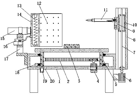
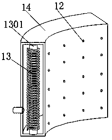
The invention belongs to the technical field of sculpture processing, and particularly relates to a manufacturing table for ceramic sculpture processing. According to the problems that under the natural conditions, the time of waiting for surface drying and hardening is too long, and the production efficiency is low, the following scheme is provided, wherein the manufacturing table comprises a workbench, an cavity is formed in the workbench, and the workbench is of a cuboid structure; a bearing mounting hole is formed in the middle of the upper surface of the workbench, and a bearing pedestalis fixed to the middle of the bottom of the workbench; the middle of the bearing pedestal and the bearing mounting hole are in clamped connection with symmetric conical roller bearings, and the same supporting ring is rotationally connected with the two conical roller bearings; and a rotating disc is fixed to the top end of the supporting ring. When the surface of a sculpture on the rotating discneeds to be rapidly dried during use, only an electric heating wire in an arc plate is heated, heat can be radiated to the surface of the sculpture at this moment, the distance between the surface ofthe sculpture and a heat source can be equal through the arranged arc plate, and the distance can be adjusted.

Description

technical field [0001] The invention relates to the technical field of sculpture processing, in particular to a production table for pottery sculpture processing. Background technique [0002] Existing sculptures often require a workbench to carve sculpture products, but for huge products, many workers use human-shaped ladders, which is not only dangerous, but also needs to be replaced with human-shaped ladders of different heights, which is very inconvenient and cannot be shared by multiple people. The operation is carried out on the workbench, and the height cannot be adjusted, nor can it be adjusted left and right, which brings inconvenience to people. [0003] After retrieval, the Chinese patent number is CN201811289693.5, which discloses a device for sculpture processing, including a processing cylinder, a motor is fixed inside the processing cylinder, a worktable is fixedly connected to the upper end of the output shaft of the motor, and two cylinders are fixedly conne...

Claims


Application Information

Patent Timeline
Patent Type & Authority Applications(China)
IPC IPC(8): B28B11/08B28B11/24B44B1/00B44B1/06
CPCB28B11/08B28B11/243B44B1/00B44B1/06
Inventor 张天宇陈春友
Owner 浙江盛元文化艺术有限公司
Learn More