
Clutch and method for the production thereof

A technology for couplings and driven shafts, applied in the direction of couplings, elastic couplings, rigid shaft couplings, etc., can solve problems such as uneven layer thickness, reduced heat dissipation, and inability to fully interrupt electrical contact , to achieve the effect of simple cost

Active Publication Date: 2020-03-31
KWD KUPPLUNGSWERK DRESDEN
View PDF7 Cites 0 Cited by
  • Summary
  • Abstract
  • Description
  • Claims
  • Application Information

AI Technical Summary

Problems solved by technology

[0010] A disadvantage of the solutions in the prior art is that, in the case of electrical insulation between the drive side and the driven side of the coupling using an insulating layer, the electrical contact cannot be sufficiently interrupted to prevent voltage flashovers, the reason being, inter alia The accessible capacitance of the insulating layer is too high
[0011] Another disadvantage is that the insulating layers of the couplings of the prior art usually have only non-uniform layers and / or non-uniform layer thicknesses, so that these places form areas of poor insulation and determine the electrical characteristics of the entire coupling
[0012] It is also disadvantageous that the insulating layer in the prior art is usually arranged in the immediate vicinity of the ring gear, which is particularly disadvantageous in that, in addition to the desired electrical insulation, thermal insulation also takes place, which leads to a significant drop in the heat dissipation required for operation, As a result, the temperature of the coupling is higher

Method used


Image

  • Clutch and method for the production thereof

Examples


example 1

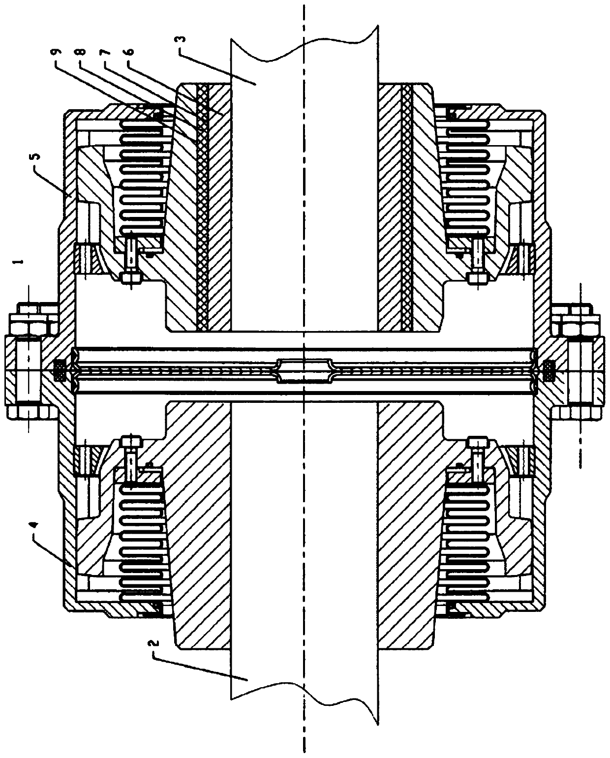
[0078] Gear coupling 1 is used to connect drive shaft 2 and driven shaft 3 . For example, the drive shaft 2 may be a motor shaft and the driven shaft 3 may be a propeller shaft of the vehicle. The gear coupling 1 essentially consists of two coupling halves 4 , 5 , one on the drive side 2 and the other on the output side 3 .

[0079] The coupling half 4 on the drive side 2 is unchanged from the prior art gear coupling. The coupling half 5 on the output side 3 has a structure according to the invention.

[0080] The inner diameter of the first inner hollow cylinder 6 made of steel corresponds to the outer diameter of the driven shaft 3 .

[0081] The first hollow cylinder 6 has a wall thickness of 14 mm and a length of 65 mm. With the aid of the knurling arranged parallel to the axis of rotation of the output shaft 3 , ribbed knurling 7 is introduced on the entire outer surface of the first hollow cylinder 6 . The ribs arranged parallel to each other had a height of 0.6 mm a...


PUM

PropertyMeasurementUnit
thicknessaaaaaaaaaa

Abstract

The invention relates to the field of mechanical engineering and relates to a clutch as can be used, for example, in vehicle drives, in particular rail vehicle drives. It is the problem of the presentinvention to specify a clutch, by way of which the electric contact between the drive side and the output side of the clutch is prevented reliably, and to specify a simple and inexpensive method forthe production thereof. The problem is solved by way of a clutch, at least consisting of a clutch half on the drive side and a clutch half on the output side, wherein at least one clutch half has at least two hollow cylinders which are arranged above one another and are arranged in a bore of the clutch half, wherein the second hollow cylinder consists of electrically insulating material, and wherein at least the first hollow cylinder, at least on its outer circumferential surface, and at least the inner circumferential surface of the bore have knurling at least in part.

Description

technical field [0001] The invention relates to the field of mechanical engineering and relates to a coupling, for example as a gear coupling, a flange coupling, an annular disc coupling, a plate coupling, an all-metal coupling, a membrane Disc couplings, multi-disc couplings, friction couplings or combination couplings that transmit torque between two machine shafts are used, for example, in vehicle drives, in particular rail vehicle drives, the invention also relates to A method of manufacturing a coupling. Background technique [0002] Shaft couplings are known in the prior art. These couplings are used to transfer torque from one shaft to another. Such couplings can be, for example, rigid or elastic couplings or switchable or non-switchable couplings. Such couplings are also used for rigid, torsionally rigid, elastic, torsionally elastic and / or movable connections between two shafts, wherein torque fluctuations and / or angular errors between the shafts can be compensat...

Claims


Application Information

Patent Timeline
Patent Type & Authority Applications(China)
IPC IPC(8): F16D3/18F16D1/00F16D1/06F16D1/02
CPCF16D1/02F16D3/185F16D13/00Y10S464/90Y10S29/023Y10T403/472Y10S264/77
Inventor M·克朗多夫T·汉奈尔
Owner KWD KUPPLUNGSWERK DRESDEN
Learn More