
Pressure-free pulse electromagnetic valve and induction liquid receiving machine with same

A pulse solenoid valve and solenoid valve technology, applied in the field of solenoid valves, can solve problems such as the inability to realize liquid control, pulse solenoid valve technology to control the opening and closing of liquid in pipelines, and achieve reliable sealing, reduced sliding friction resistance, and sensitive and reliable work. Effect

Inactive Publication Date: 2020-03-31
林坚
View PDF0 Cites 0 Cited by
  • Summary
  • Abstract
  • Description
  • Claims
  • Application Information

AI Technical Summary

Problems solved by technology

[0002] Because the existing pulse solenoid valve controls the opening and closing of the valve port through the pulse electric signal, its working performance is stable, the trigger is fast, the power consumption is low, and the service life is long. It is more and more used in automatic control occasions, such as conventional induction Faucet, but the existing pulse solenoid valve requires a certain working pressure when it works, generally rated between 0.1-0.8MPa, because it is controlled by a small hole pilot, and the seal is realized by the pressure of the liquid in the pipeline. Open and close, so as to realize the opening and closing of the liquid in the pipeline controlled by the pulse solenoid valve, so when the existing pulse solenoid valve is used as the control part for the opening and closing of the liquid pipeline, the liquid in the pipeline needs a certain pressure to work normally, such as people Commonly used induction faucets controlled by pulse solenoid valves generally require the water pressure in the pipeline to be above 0.1MPa before the induction faucets can work normally. When people use bottled water, or other liquid beverages or liquid seasonings, etc. If the pressure is increased or pressurized by a liquid pump, the opening and closing of the liquid in the pipeline cannot be controlled by the existing pulse solenoid valve technology, that is to say, the pulse solenoid valve of the prior art cannot realize the liquid in the non-pressurized state. controlled

Method used


Image

  • Pressure-free pulse electromagnetic valve and induction liquid receiving machine with same
  • Pressure-free pulse electromagnetic valve and induction liquid receiving machine with same
  • Pressure-free pulse electromagnetic valve and induction liquid receiving machine with same

Examples


Embodiment 1

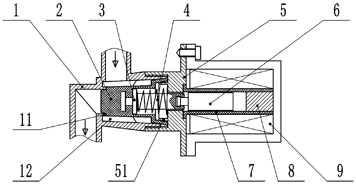
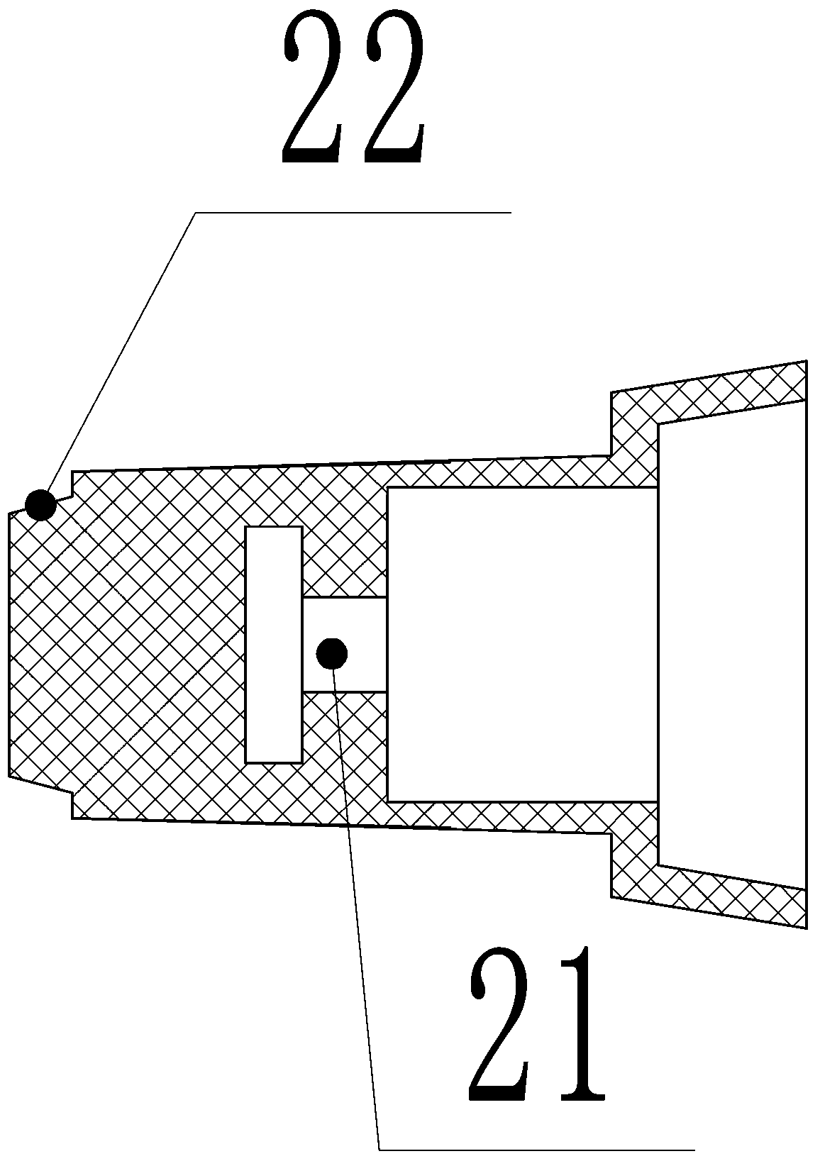
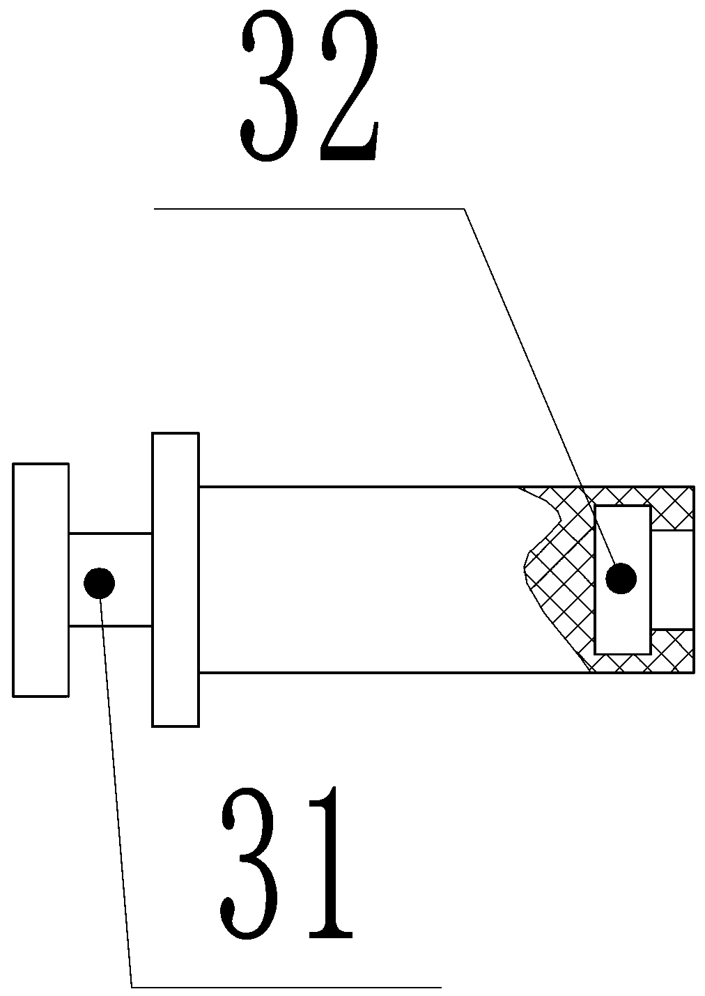
[0030]Embodiment 1, a pressureless pulse solenoid valve, said a pressureless pulse solenoid valve includes a valve body 1, a sealing plug 2, a pull rod 3, a spring 4, a valve cover 5, an electromagnet core 6, a permanent magnet 8, Coil winding 9, the valve body 1 is a corner or straight-through valve body, a cylindrical hole perpendicular to it is provided on the flow channel cross section of the valve body 1, and a raised sealing ring line 11 is provided at the bottom of the cylindrical hole, A supporting rib 12 is provided on the circumferential side wall at the bottom of the cylindrical hole. The sealing plug 2 is a cover with a thick bottom and a thin side wall. An inner annular groove 21 is provided on the inner side of the bottom of the sealing plug 2. The pull rod 3 It is a stepped pull rod, one end is large and the end is small, and an outer annular groove 31 is provided at the large end, and an inner annular groove 32 is provided at the small end. The valve cover 5 is ...

Embodiment 2

[0037] Embodiment 2, an induction liquid receiver with the non-pressure pulse solenoid valve, including the solenoid valve assembly 10, a liquid receiver housing 20, a pulse signal infrared induction probe 30, and the liquid receiver housing 20 It is a tubular casing, and a partition 201 is arranged in the middle of the tubular casing. The partition 201 divides the liquid receiver housing 20 into upper and lower chambers, and the upper chamber holds the liquid. The partition 201 and the liquid contact The casing 20 is an integral component, and the solenoid valve assembly 10 is arranged on the lower side of the partition 201, and the solenoid valve assembly 10 is fastened on the lower side of the partition 201 by nuts or screws. The liquid inlet of 10 is connected with the liquid in the upper cavity, and a cover plate 202 is arranged on the lower side of the solenoid valve assembly 10, and the cover plate 202 is fastened on the solenoid valve assembly 10 by nuts or screws. The...

Embodiment 3

[0043] Embodiment 3, the liquid-contacting machine housing 20 is integrated with the valve body 1 of the solenoid valve, the partition plate 201 and the lower cover plate 202, and the gasket 205 and the connecting gasket 205 are omitted at the same time. nuts or screws.

[0044] When in use, the user can approach or leave the liquid-contacting spoon or cup to trigger the pulse signal infrared sensor probe, and the pulse signal infrared sensor probe will give the solenoid valve assembly a pulse signal to control its opening and closing.


PUM


Abstract

The invention discloses a pressure-free pulse electromagnetic valve. The pressure-free pulse electromagnetic valve comprises a valve body, a sealing plug, a pull rod, a spring, a valve cover, an electromagnet core, a permanent magnet and a coil winding, the sealing plug is directly pulled through the electromagnet core without pilot control through the small hole and can normally work under no pressure; and the induction liquid receiving machine with the pressure-free pulse electromagnetic valve comprises an electromagnetic valve assembly, a liquid receiving machine shell and a pulse signal infrared sensing probe, a user can close or leave to trigger the pulse signal infrared sensing probe by using a liquid receiving spoon or cup and the like, and the pulse signal infrared sensing probe gives pulse signal to the electromagnetic valve assembly to control the opening and closing of the electromagnetic valve assembly.

Description

technical field [0001] The invention relates to the technical field of solenoid valves, in particular to a non-pressure pulse solenoid valve and an induction liquid receiving machine with the solenoid valve. Background technique [0002] Because the existing pulse solenoid valve controls the opening and closing of the valve port through the pulse electric signal, its working performance is stable, the trigger is fast, the power consumption is low, and the service life is long. It is more and more used in automatic control occasions, such as conventional induction Faucet, but the existing pulse solenoid valve requires a certain working pressure when it works, generally rated between 0.1-0.8MPa, because it is controlled by a small hole pilot, and the seal is realized by the pressure of the liquid in the pipeline. Open and close, so as to realize the opening and closing of the liquid in the pipeline controlled by the pulse solenoid valve, so when the existing pulse solenoid val...

Claims


Application Information

Patent Timeline
IPC IPC(8): F16K31/66F16K1/32
CPCF16K1/32F16K31/002F16K31/06F16K31/0655F16K31/0675
Inventor 林坚
Owner 林坚
Learn More