A device for making reed contacts

A technology for making devices and electrical contacts, applied in the directions of measuring devices, connections, circuits, etc., can solve the problems of troublesome assembly process, small overall structure, and failure rate of defective products, so as to facilitate the assembly of electrical contacts and reduce the difficulty of installation.

Active Publication Date: 2021-03-26
JINAN JINBAOMA ELECTRONICS INSTR CO LTD
View PDF6 Cites 0 Cited by
  • Summary
  • Abstract
  • Description
  • Claims
  • Application Information

AI Technical Summary

Problems solved by technology

Because the electrical contacts should be installed in the pressure gauge, and because of its small overall structure, the current assembly process is basically purely manual operation, which is troublesome, especially the failure and defective products caused by unskilled workers. Very high rate

Method used


Image

  • A device for making reed contacts
  • A device for making reed contacts
  • A device for making reed contacts

Examples


Embodiment 1

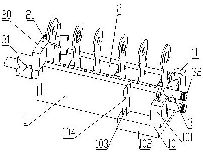
[0046] see figure 1 and image 3 , the present invention provides a dry reed electric contact manufacturing device, the present invention provides a dry reed electric contact manufacturing device, including a base 1, and a clamp assembly, the base 1 is provided with a placement groove 2 for placing an electric contact support structure, When in use, the lower part of the electric contact bracket structure is placed in the placement groove 2, one end of the base 1 is a closed end, and the other end is an open end;

[0047] The inside of the base 1 is provided with a rubber delivery tube 3, which is set horizontally, and the rubber delivery tube 3 corresponds to the electrical contact installation hole reserved at the lower part of the electric contact bracket structure. And the material barrel, the other end is a closed end, and several glue outlet holes are arranged along the axis of the rubber pipe 3, and the glue outlet holes are all opened upwards;

[0048] The clamp comb...

Embodiment 2

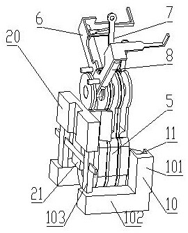
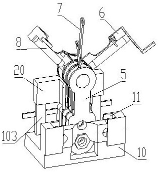
[0076] On the basis of Embodiment 1, the reed electric contact corresponding to the reed electric contact manufacturing device includes a bracket 5, and the upper part of the bracket 5 is provided with a horizontal shaft rod, and the shaft rod is rotated to connect two devices for setting the upper and lower limits of the pressure gauge. One end of the fixed needle 6 and the movable needle 7, the reed switch 8 is fixed on the setting needle 6, and the setting needle 6 is a bent strip plate body, including the bottom plate at the bottom, and the bottom end of the bottom plate rotates with the shaft connection, the middle plate and the upper plate are arranged in sequence above the bottom plate, the plates of the middle plate and the bottom plate are vertical, the plates of the upper plate and the bottom plate are parallel, and the reed switch 8 is fixedly arranged on the plate body of the bottom plate, and the reed switch The axis of 8 is parallel to the plate surface of the bot...


PUM


Abstract

The invention discloses a reed electric contact manufacturing device, and relates to the field of detection equipment. The technical scheme is characterized in that the reed electric contact manufacturing device comprises a base and a clamp combination, wherein a placement groove for placing an electric contact bracket structure body is formed in the base; a glue conveying pipe is arranged in thebase in a penetrating mode; one end of the glue conveying pipe is a glue inlet end and is connected with a glue conveying pump and a charging barrel through a pipeline, and a plurality of glue outletholes are formed in an array mode along the axis of the glue conveying pipe and are upwards formed; the clamp combination comprises a lower clamp and an upper clamp which can be disassembled and combined; the lower clamp corresponds to the end structure block body of the electric contact bracket structure body, and the lower clamp is provided with a slot corresponding to the end structure block body mounting wing plate; and the upper clamp is connected with the lower clamp in an inserted mode. The beneficial effects of the reed electric contact manufacturing device are that the reed electric contact manufacturing device can achieve the convenient assembly of an electric contact, and can also be used and operated by a non-skilled worker quickly.

Description

technical field [0001] The invention relates to the field of detection equipment, in particular to a dry reed electric contact manufacturing device. Background technique [0002] The reed switch electrical contact is mainly used in pressure gauges as an alarm trigger mechanism for the pressure gauge to reach the set value. By setting the reed switch electrical contact in the pressure gauge, the upper and lower limits of the pressure gauge can be set according to the site conditions. The watch needle drives the movable needle of the electric contact to move synchronously. When the gauge needle reaches the upper or lower limit set by the electric contact during the use of the pressure gauge, the watch needle drives the movable needle to trigger the reed switch to be connected, thereby triggering the alarm circuit. [0003] The electrical contacts include the main bracket and two movable pins and two setting pins set on the main bracket. In order to avoid interference in the mo...

Claims


Application Information

Patent Timeline
Patent Type & Authority Patents(China)
IPC IPC(8): H01R43/00G01L19/12G01L1/00
CPCG01L1/00G01L19/12H01R43/007
Inventor 王浩阎乐囡
Owner JINAN JINBAOMA ELECTRONICS INSTR CO LTD
Why Eureka
Try Eureka