
Steam turbine rotor system instability limit rapid prediction method based on shroud ring zero damping

A steam turbine rotor, zero damping technology, used in the testing of machine/structural components, static/dynamic balance testing, measuring devices, etc., can solve the problems of large error, complex vibration, inability to accurately obtain the shroud and the entire rotor system, etc.

Active Publication Date: 2020-03-27
SHANDONG UNIV
View PDF11 Cites 2 Cited by
  • Summary
  • Abstract
  • Description
  • Claims
  • Application Information

AI Technical Summary

Problems solved by technology

However, the inventors of this patent have found through in-depth research that the final stage blades of the low-pressure rotor of large-scale nuclear / thermal power steam turbines in actual operation are in wet steam, and they are subjected to more complex fluid multi-frequency excitations in addition to the simple harmonic excitation related to the rotor speed. However, the vibration of the shroud driven by the blade under multi-frequency excitation is far more complicated than that of a single harmonic excitation. According to the generation of shroud damping and the vibration suppression mechanism: the vibration of the blade under the multi-frequency excitation of fluid such as wet steam drives the movement of the shroud to make the adjacent shroud move. The friction of the belt contact surface produces energy consumption and vibration suppression, that is, the shroud damping mainly depends on the vibration response of the blade under the excitation of the actual operation, which has a significant excitation-dependent nonlinearity, and the vibration under the multi-frequency excitation of fluid such as wet steam The influence of the response on the shroud damping cannot be ignored, and the design of the shroud structure of the blade shroud of a large steam turbine unit using the existing technology such as the quantitative calculation method of the shroud damping induced by a single harmonic excitation will lead to excessive errors due to serious deviations from the actual working conditions. However, at present, due to the limitation of the technical level of the test, neither the field test nor the laboratory test can accurately obtain the damping characteristics of the shroud and the entire rotor system (including rotating parts such as shafts, blades, shrouds, and bearing supports, hereinafter referred to as the rotor system). , the lack of shroud damping calculation methods and instability limit prediction methods that can consider the influence of multi-frequency excitation of fluids such as wet steam has become a bottleneck that seriously affects the design quality of steam turbines and their key components, leading to safety hazards such as operational instability. Can accurately design the shroud structure and its damping characteristics, predict whether the shroud can play the expected role of damping, suppressing vibration and increasing stability under multi-frequency excitation in actual operation, and establish the instability limit of the rotor system suitable for the characteristics of large steam turbine units with shrouds The rapid prediction method has important theoretical significance and engineering application value

Method used

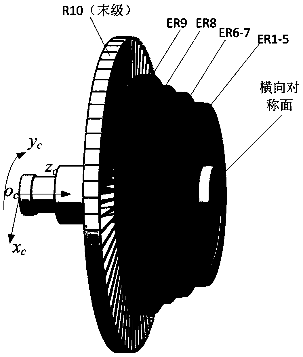
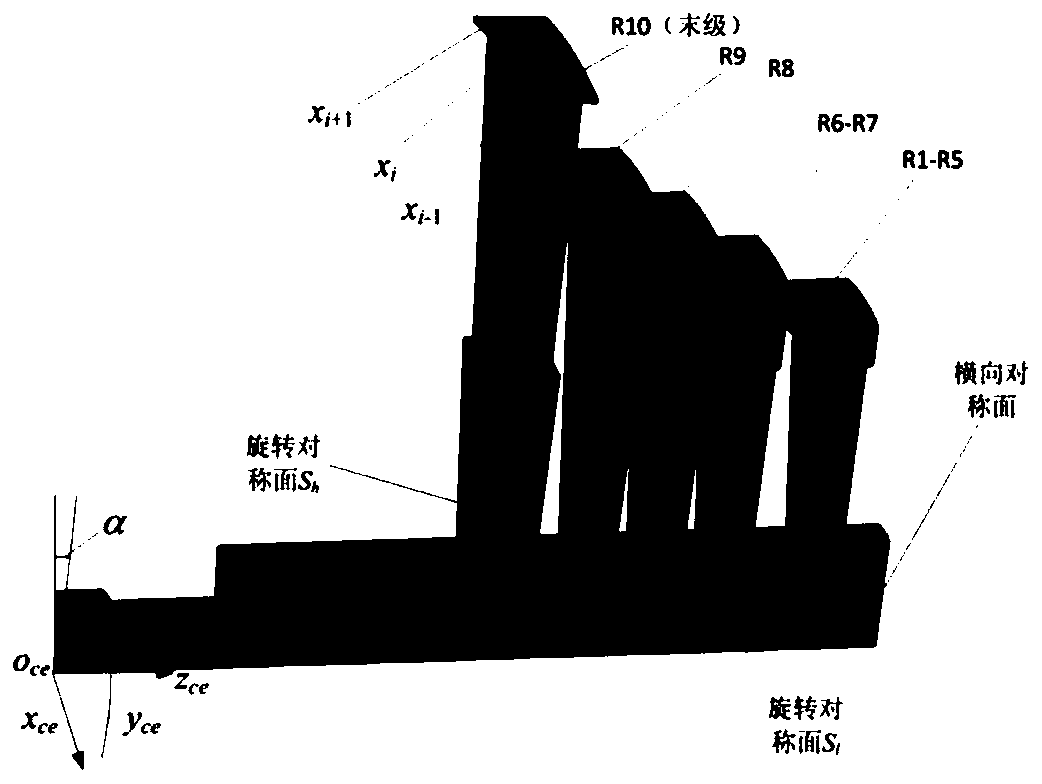

Image

  • Steam turbine rotor system instability limit rapid prediction method based on shroud ring zero damping
  • Steam turbine rotor system instability limit rapid prediction method based on shroud ring zero damping
  • Steam turbine rotor system instability limit rapid prediction method based on shroud ring zero damping

Examples


Embodiment 1

[0028] Embodiment 1. This embodiment provides a rapid prediction method for the instability limit of the steam turbine rotor system based on zero damping of the shroud;

[0029] A rapid prediction method for the instability limit of the steam turbine rotor system based on the zero damping of the shroud, including:

[0030] S1: Construct the equivalent model of the shroud damping of the steam turbine rotor system under multi-frequency excitation and the quantitative calculation formula of the shroud damping;

[0031] S2: According to the structure of the steam turbine rotor system, calculate the modal mass of the steam turbine rotor system and the natural frequency ignoring the shroud damping;

[0032] S3: Use flow field simulation to obtain the multi-frequency excitation force of the steam turbine rotor system under a certain operating condition, convert the multi-frequency excitation force into the superposition of harmonic excitation components of multiple orders and differe...


PUM


Abstract

The invention discloses a steam turbine rotor system instability limit rapid prediction method based on shroud ring zero damping. The steam turbine rotor system instability limit rapid prediction method includes the steps: establishing a three-dimensional geometric model of a steam turbine rotor system; adopting a modal analysis module and a transient response analysis module of finite element software; and reading adjacent peak values (A1 and A2) of blade transient displacement response through a maximum vibration displacement response curve of the system, calculating a logarithm reduction delta and a damping ratio xi of the rotor system considering the shroud friction effect under the rotating speed and each-order harmonic excitation load, and quantitatively calculating shroud damping Csunder different rotating speeds. The steam turbine rotor system instability limit rapid prediction method utilizes an FFT multi-harmonic balance method, and expands and applies existing girdle damping modeling considering the influence of simple harmonic excitation and a quantitative solving method based on a transient response envelope line to multi-frequency excitation. The steam turbine rotorsystem instability limit rapid prediction method is clear in operation process and high in calculation efficiency, provides theoretical basis and method for design and manufacturing of the turbine rotor system, and has important theoretical significance and engineering application value for ensuring safe operation of the turbine.

Description

technical field [0001] The disclosure relates to the field of steam turbine rotor stability prediction, in particular to a fast prediction method for instability limit of a steam turbine rotor system based on shroud zero damping. Background technique [0002] The statements in this section merely mention background art related to the present disclosure and do not necessarily constitute prior art. [0003] The large steam turbine rotor system has complex structural features such as heavy duty, long shafting, large-size flexible blades and shrouds. The operating speed is usually above the critical speed of the first to second order. During operation, the large flexible blades are prone to bending and torsional vibration and casing Rubbing will seriously endanger the safe and stable operation and service life of the entire unit. There are many cases in domestic and foreign power plants that the unit shut down due to blade vibration failure and caused huge losses. At present, ...

Claims


Application Information

Patent Timeline
IPC IPC(8): G06F30/20G01M1/16
CPCG01M1/16
Inventor 唐委校李南宜郭冰王恒
Owner SHANDONG UNIV
Learn More