
Method and device for predicting fatigue crack propagation direction of aircraft structure

A technology of fatigue crack growth and aircraft structure, applied in the direction of instruments, electrical digital data processing, geometric CAD, etc., can solve problems affecting the safety of aircraft use

Pending Publication Date: 2020-03-27
XIAN AIRCRAFT DESIGN INST OF AVIATION IND OF CHINA
View PDF0 Cites 0 Cited by
  • Summary
  • Abstract
  • Description
  • Claims
  • Application Information

AI Technical Summary

Problems solved by technology

If these fatigue cracks are not taken action and allowed to grow, it may affect the safety of the aircraft

Method used


Image

  • Method and device for predicting fatigue crack propagation direction of aircraft structure
  • Method and device for predicting fatigue crack propagation direction of aircraft structure
  • Method and device for predicting fatigue crack propagation direction of aircraft structure

Examples


Embodiment

[0057] The present invention will be further described in detail with a specific example below.

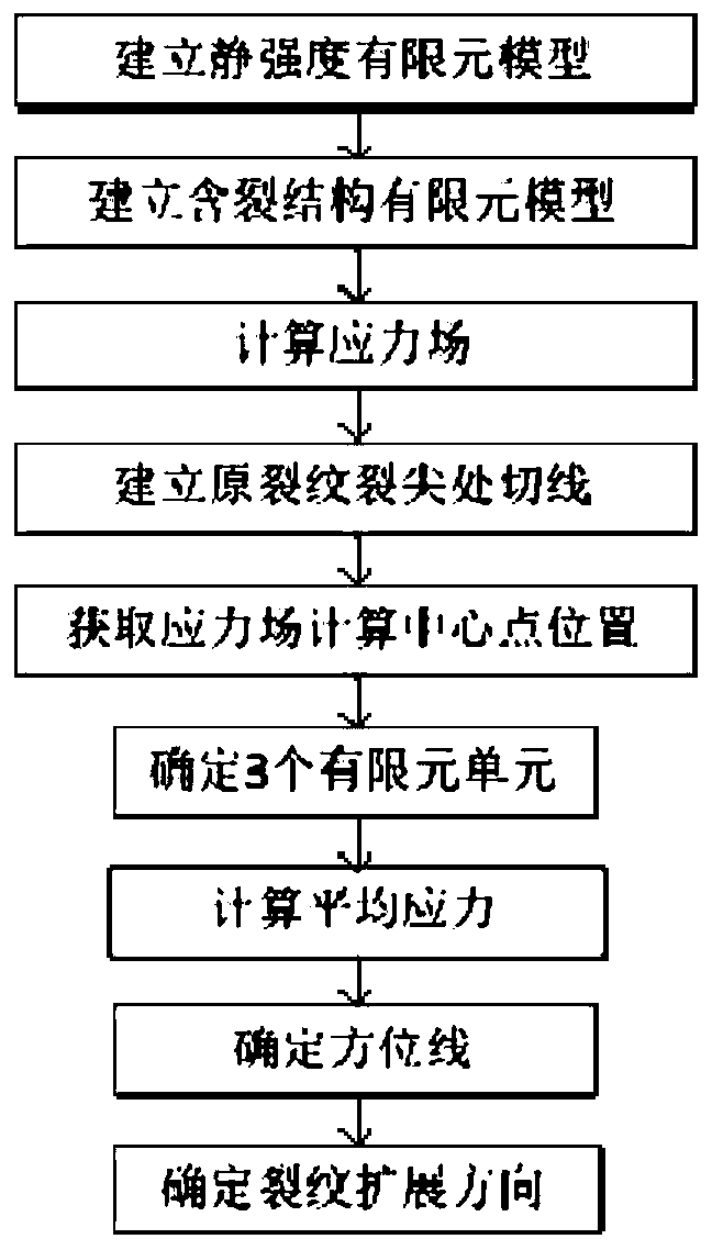
[0058] A method for predicting the direction of fatigue crack growth in aircraft structures based on finite elements, comprising the following steps:

[0059] It is known that the thickness of a skin structure is t=1mm, the crack length a=20mm, and the material of the skin structure is 2024.

[0060] Predict the fatigue crack growth direction of the aircraft skin structure.

[0061] Step 1: Establish a static strength finite element model. Reasonably select the structural analysis area, select the appropriate unit type, simulate the support and constraints of the structure, apply real loads, and establish a static strength finite element model.

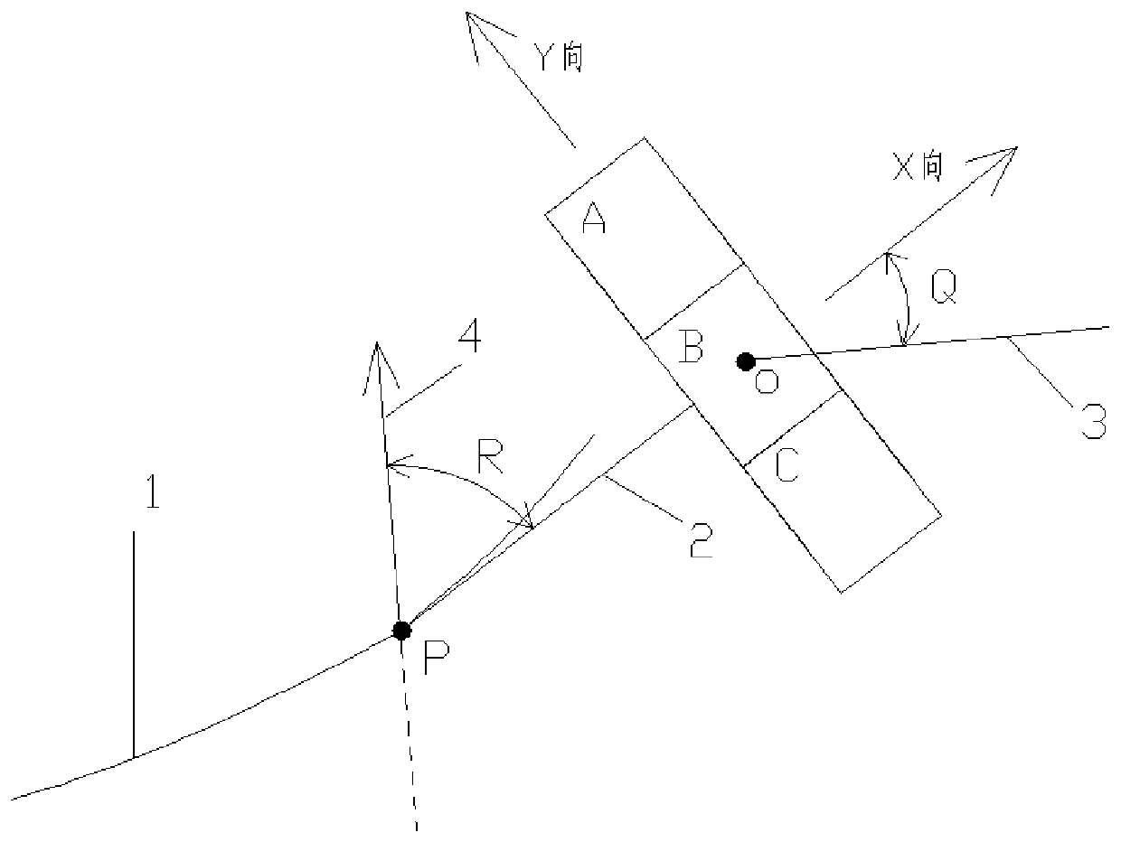
[0062] Step 2, establishing a finite element model of the structure containing cracks. In the static strength finite element model established in step 1, cracks are introduced according to the real crack trajectory curve, the initial c...


PUM


Abstract

The invention provides a method and device for predicting the fatigue crack propagation direction of an aircraft structure. The method includes the steps: establishing a finite element model of a crack-containing structure, and carrying out stress field calculation; predicting the fatigue crack propagation direction of the structure by determining the position of a stress field calculation centerpoint, and determining a finite element unit required by far-end stress field calculation; and calculating the average stress at the far-end stress field calculation center, and calculating the azimuth angle where the principal stress of the far-end stress field calculation center is located. The method is correct in theoretical basis, clear in engineering concept and simple and convenient to use.The finite element-based aircraft structure fatigue crack propagation direction prediction method can rapidly predict a cracking expansion mode in the aircraft structure design stage or the fatigue crack expansion direction after cracks occur to the structure in the flight process, and therefore the problem that the fatigue crack expansion direction of the aircraft structure is not easy to predict is solved.

Description

technical field [0001] The invention relates to the field of aircraft design, in particular to a method and device for predicting the fatigue crack propagation direction of an aircraft structure. Background technique [0002] During the flight of the aircraft, various possible fatigue cracks will inevitably appear. If these fatigue cracks are not taken measures but allowed to grow, it may affect the safety of the aircraft. [0003] In the structural design stage, if the possible cracking mode of the structure can be predicted in advance, by setting the crack arresting ribs in advance in the crack propagation direction of the structural member, etc., and taking appropriate crack arrest measures, the crack growth can be effectively delayed or prevented. In the flight phase, once cracks appear in the structure, if the direction of crack propagation can be quickly predicted, it can not only quickly predict the structural damage that may be caused by further crack expansion, but...

Claims


Application Information

Patent Timeline
IPC IPC(8): G06F30/15G06F30/23G06F119/14
Inventor 翟新康田小幸
Owner XIAN AIRCRAFT DESIGN INST OF AVIATION IND OF CHINA
Learn More