Targeted shear wave elastography detection system and detection method thereof

An elastography and detection system technology, applied in measuring devices, processing response signals of detection, and analyzing solids using sonic/ultrasonic/infrasonic waves, etc., can solve problems such as accuracy and reliability, hindering ultrasonic transmission, and affecting the sensitivity of shear wave elastography. , to achieve the effect of improving penetration, improving sensitivity, and accurate and reliable detection results.

Active Publication Date: 2020-03-27
SHENZHEN UNIV
View PDF12 Cites 2 Cited by
  • Summary
  • Abstract
  • Description
  • Claims
  • Application Information

AI Technical Summary

Problems solved by technology

[0003] Shear wave elastography is generally obtained through the processing of an ultrasonic imaging system. The elastography detection system in the prior art mainly tests the test body through an ultrasonic transducer, and then collects information through the ultrasonic imaging system for shear wave elastography. The interior of different test bodies will have different structures and components, and the different structures and components inside the test body may hinder the transmission of ultrasonic waves, thereby affecting the sensitivity of shear wave elastography detection. The elastography system in the prior art cannot Accurate and reliable shear wave elastography results for all test bodies

Method used


Image

  • Targeted shear wave elastography detection system and detection method thereof
  • Targeted shear wave elastography detection system and detection method thereof
  • Targeted shear wave elastography detection system and detection method thereof

Examples


Embodiment Construction

[0027] In order to further understand the features, technical means, and specific objectives and functions achieved by the present invention, the present invention will be further described in detail below in conjunction with the accompanying drawings and specific embodiments.

[0028] refer to Figure 1 to Figure 4 .

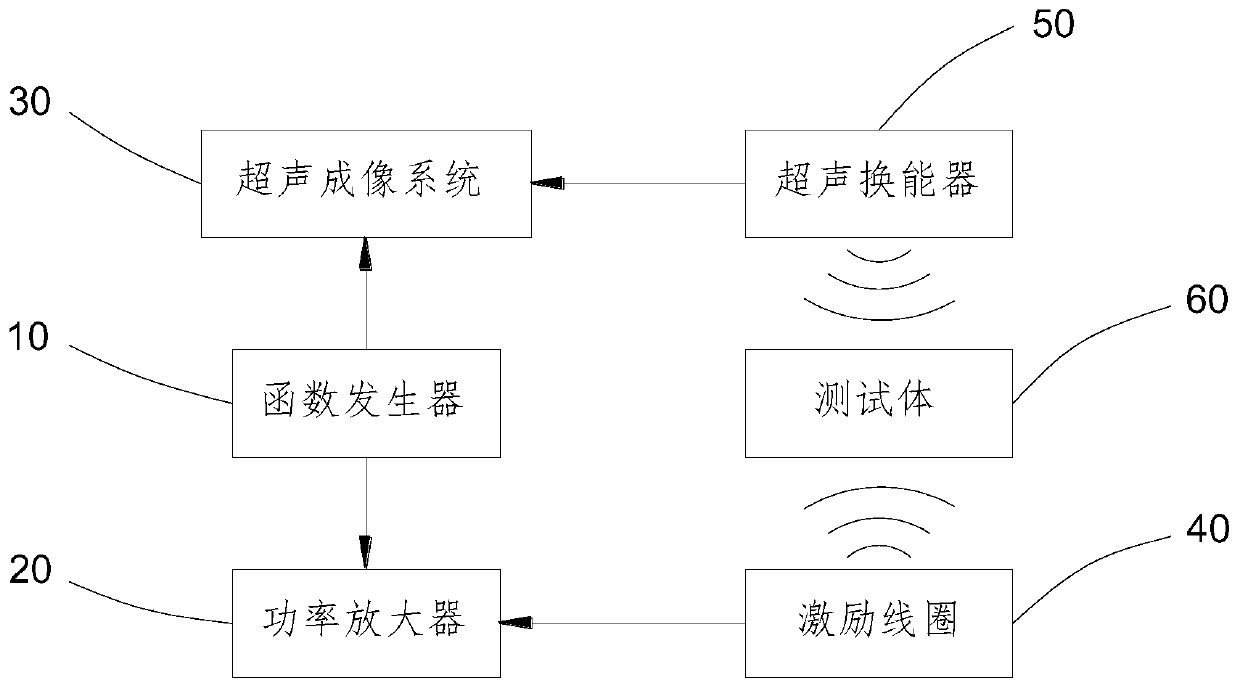
[0029] The embodiment of the present invention discloses a targeted shear wave elastography detection system, such as figure 1 As shown, it includes a function generator 10, the output end of the function generator 10 is respectively connected to a power amplifier 20 and an ultrasonic imaging system 30, the output end of the power amplifier 20 is connected to an excitation coil 40, and the data acquisition end of the ultrasonic imaging system 30 is connected to a Between the ultrasonic transducer 50 and the excitation coil 40 and the ultrasonic transducer 50, a test body 60 containing magnetic particles inside is provided.

[0030] In this embodiment, the ult...


PUM

PropertyMeasurementUnit
shear modulusaaaaaaaaaa

Abstract

The invention provides a targeted shear wave elastography detection system and a detection method thereof. Magnetic particles are injected into a test body, and the test body is placed between an ultrasonic transducer and an excitation coil; the function generator transmits a square wave to the power amplifier and transmits a trigger signal to the ultrasonic imaging system at the same time; the power amplifier amplifies the square wave, the excitation coil generates a pulsed magnetic field acting on the test body, and the magnetic field drives the magnetic particles in the test body to vibrate; the ultrasonic imaging system triggers the ultrasonic transducer to work, and the ultrasonic transducer receives the reflection pulse to form a radio frequency echo signal; the ultrasonic imaging system collects a radio frequency echo signal from the ultrasonic transducer, demodulates and images the radio frequency echo signal, and calculates to obtain a shear wave speed c and a shear modulus G.According to the invention, magnetic particles are used as probes for marking, so that the penetrability of excitation signals in a complex environment can be effectively improved, and the detectionresult of shear wave elastic imaging detection is accurate and reliable.

Description

technical field [0001] The invention relates to elastography, and specifically discloses a targeted shear wave elastography detection system and a detection method thereof. Background technique [0002] According to different excitation methods, ultrasound elastography can be divided into quasi-static elastography, low-frequency vibration acoustic elastography, shear wave elastography, acoustic radiation force pulse imaging, fast shear wave imaging, etc. These imaging methods primarily quantify the shear modulus of tissue by measuring the shear wave velocity in the region of interest. Generally, the greater the hardness of the test body, the greater the shear wave velocity and shear modulus. [0003] Shear wave elastography is generally obtained through the processing of an ultrasonic imaging system. The elastography detection system in the prior art mainly tests the test body through an ultrasonic transducer, and then collects information through the ultrasonic imaging sys...

Claims


Application Information

Patent Timeline
Patent Type & Authority Applications(China)
IPC IPC(8): G01N29/06G01N29/50
CPCG01N29/0654G01N29/50G01N2291/02827G01N2291/0422Y02A90/30
Inventor 陈冕林浩铭陈昕陈思平胡雨阳齐亭亭王梦珂丁格陈微
Owner SHENZHEN UNIV
Why Eureka
Try Eureka