Frameless solar lamp
A solar energy, frameless technology, applied in energy-saving lighting, outdoor lighting, sustainable buildings, etc., can solve the problems of increased space occupied by components, inconvenient assembly, increased transportation costs, etc., to reduce the installation structure of lamps and the convenience of maintenance The effect of improving and improving the usability
- Summary
- Abstract
- Description
- Claims
- Application Information
AI Technical Summary
Problems solved by technology
Method used
Image
Examples
Embodiment 1
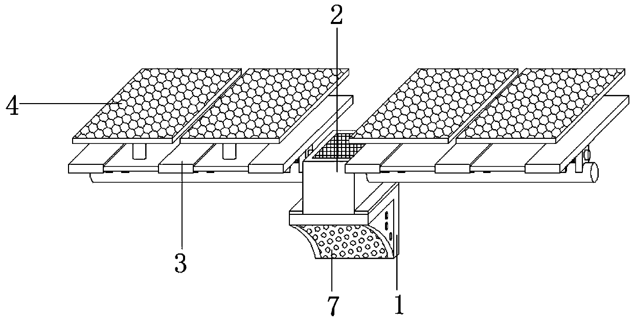
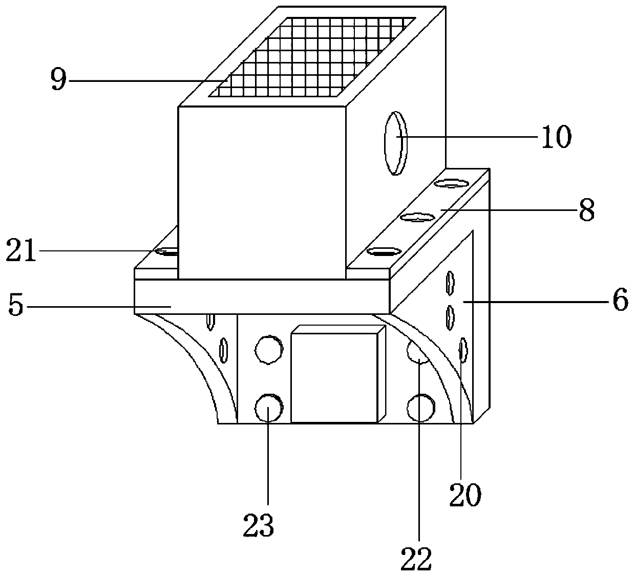
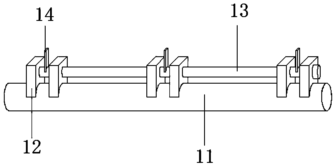
[0027] like Figure 1-Figure 4 As shown, a frameless solar lamp includes a lamp body support assembly 1, a control box 2 is provided on the top side of the lamp body support assembly 1, and an installation assembly 3 is fixedly connected to the left and right sides of the control box 2 respectively. The top side of the mounting assembly 3 is respectively provided with a first solar panel body 4, the lamp body support assembly 1 includes an L-shaped mounting plate 5, and the edges of both sides of the inner wall of the L-shaped mounting plate 5 are fixedly connected with reinforcing plates 6, and the reinforcing plate 6 The LED light source assembly 7 is fixedly connected between the inner walls of the board 6, the bottom of the left and right sides of the control box 2 is fixedly connected with the connecting plate 8, the top side of the control box 2 is provided with a connecting groove, and the control box 2 passes through the connecting groove Fixedly connected with the sec...
Embodiment 2
[0034] like Figure 5 As shown, the right side of the first flat plate 15 and the left side of the second flat plate 16 are dug with a first sliding groove 31, and the two sides of the third flat plate 17 are symmetrically dug with a second sliding groove 32. Both sides of the transparent glass plate 18 are respectively slidingly connected with the first sliding groove 31 and the second sliding groove 32, and the top sides of the first flat plate 15, the second flat plate 16, and the third flat plate 17 are equidistantly provided with limit bolts, and The first flat plate 15, the second flat plate 16, and the third flat plate 17 are attached to the top side of the transparent glass plate 18 by limit bolts respectively, and by setting the first sliding groove 31 and the second sliding groove 32, the Both sides of the transparent glass plate 18 are engaged in the inside of the first sliding groove 31 and the second sliding groove 32, and then the transparent glass plate 18 is re...
Embodiment 3
[0036] like Figure 4 As shown, the top side of the transparent glass plate 18 is equidistantly dug with thread grooves 33 respectively, and the bottom side of the outer wall of the connecting column 19 is provided with threaded protrusions, and the connecting columns 19 are respectively connected with the threaded grooves 33 through the threaded protrusions. The inner wall is connected and fixed. By setting the threaded groove 33, the connecting column 19 can be fixed inside the threaded groove 33 through the threaded protrusion, and the connecting column 19 can be assembled during the installation process. At the same time, when the parts are damaged, the The connecting column 19 is disassembled to replace the connecting column 19 or the first solar panel body 4 .
[0037] The working principle of the present invention is that the first solar panel body 4 and the second solar panel body 9 are both double-sided double-glass solar panels, which can absorb sunlight and convert ...
PUM
 Abstract
Description
Claims
Application Information
 - Generate Ideas
- Intellectual Property
- Life Sciences
- Materials
- Tech Scout
- Unparalleled Data Quality
- Higher Quality Content
- 60% Fewer Hallucinations
Browse by: Latest US Patents, China's latest patents, Technical Efficacy Thesaurus, Application Domain, Technology Topic, Popular Technical Reports.
© 2025 PatSnap. All rights reserved.Legal|Privacy policy|Modern Slavery Act Transparency Statement|Sitemap|About US| Contact US: help@patsnap.com


