
Road crack pouring machine

A seam filling machine and crack technology, applied in the field of seam filling machine, can solve the problems such as inability to clean up debris, unable to press in time, etc., and achieve good effect of joint filling and convenient adjustment

Active Publication Date: 2020-03-27
NORTH CHINA UNIVERSITY OF SCIENCE AND TECHNOLOGY
View PDF7 Cites 5 Cited by
  • Summary
  • Abstract
  • Description
  • Claims
  • Application Information

AI Technical Summary

Problems solved by technology

[0004] The purpose of the present invention is to solve the problems in the prior art that the sundries in the gaps cannot be cleaned and the gaps cannot be flattened in time after filling, and a road crack filling machine is proposed.

Method used


Image

  • Road crack pouring machine
  • Road crack pouring machine
  • Road crack pouring machine

Examples


Embodiment 1

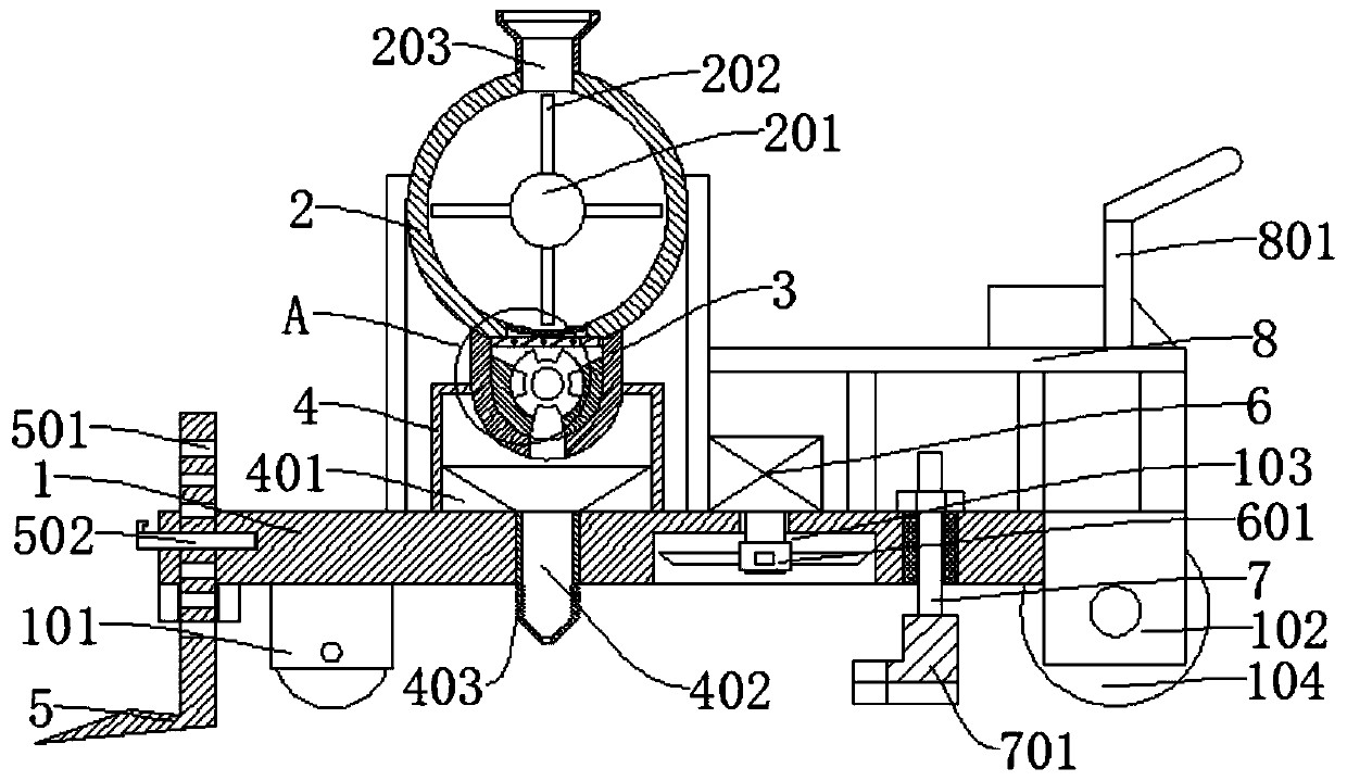
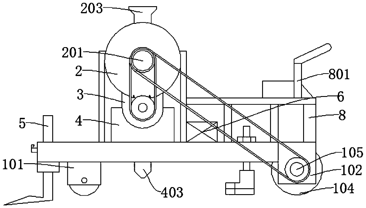
[0034] refer to Figure 1-7 , a road crack filling machine, comprising a bottom plate 1, the bottom of the bottom plate 1 is rotatably connected with a first roller 101, the outer wall of the bottom plate 1 is connected with a fixed plate 102, the inner wall of the fixed plate 102 is connected with a first rotating shaft 105, the first The outer wall of the rotating shaft 105 is connected with a second roller 104;

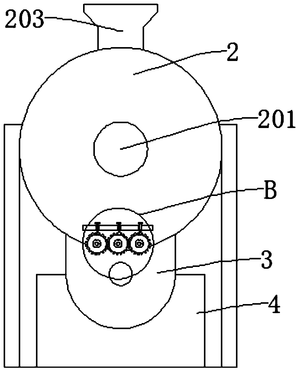
[0035] The top of the bottom plate 1 is connected with the mixing drum 2 through the fixed rod, the mixing drum 2 is connected with the stirring piece, the bottom of the mixing drum 2 is provided with a filter screen 204, and the bottom of the mixing drum 2 is also provided with a quantitative cylinder 3 connected thereto. The bottom of the quantitative cylinder 3 is provided with a discharge hole 305;

[0036] The top outer wall of the bottom plate 1 is also fixedly connected with a discharge box 4, the discharge box 4 is connected to the bottom outer wall of the...

Embodiment 2

[0040] refer to Figure 1-7 , a road crack filling machine, comprising a bottom plate 1, the bottom of the bottom plate 1 is rotatably connected with a first roller 101, the outer wall of the bottom plate 1 is connected with a fixed plate 102, the inner wall of the fixed plate 102 is connected with a first rotating shaft 105, the first The outer wall of the rotating shaft 105 is connected with a second roller 104;

[0041] The top of the bottom plate 1 is connected with the mixing drum 2 through the fixed rod, the mixing drum 2 is connected with the stirring piece, the bottom of the mixing drum 2 is provided with a filter screen 204, and the bottom of the mixing drum 2 is also provided with a quantitative cylinder 3 connected thereto. The bottom of the quantitative cylinder 3 is provided with a discharge hole 305;

[0042] The top outer wall of the bottom plate 1 is also fixedly connected with a discharge box 4, the discharge box 4 is connected to the bottom outer wall of the...


PUM


Abstract

The invention discloses a road crack pouring machine, and belongs to the field of crack pouring machines. A road crack pouring machine comprises a bottom plate, the bottom of the bottom plate is rotationally connected with first rolling wheels, the outer wall of the bottom plate is connected with a fixing plate, the inner wall of the fixing plate is connected with a first rotating shaft, and the outer wall of the first rotating shaft is connected with second rolling wheels; the top of the bottom plate is connected with a stirring cylinder through a fixing rod, a stirring part is connected intothe stirring cylinder, and a discharging hole is formed in the bottom of the quantifying cylinder. A discharging box is further fixedly connected to the outer wall of the top of the bottom plate, a discharging pipe is further connected to the bottom of the discharging box, and a telescopic pipe is connected to the bottom of the discharging pipe; the bottom plate is further connected with a shovelplate in a sliding mode. According to the crack pouring device, impurities in cracks can be removed firstly, the crack pouring effect is enhanced, the cracks can be flattened in time after crack pouring, the pavement subjected to crack pouring is firmer. Meanwhile, asphalt can be stirred, the asphalt is prevented from being accumulated and solidified together, and the crack pouring device is better used.

Description

technical field [0001] The invention relates to the technical field of seam filling machines, in particular to a seam filling machine for road cracks. Background technique [0002] Asphalt road is a general term for pavements that use asphalt as a binder to pave the surface. Asphalt road is a pavement structure in which a certain thickness of asphalt mixture is paved on a flexible base and a semi-rigid base. Compared with gravel roads, the strength and stability of asphalt roads are greatly improved; compared with cement concrete roads , The asphalt road surface is smooth and seamless, the driving vibration is small, the noise is low, the traffic is open quickly, the maintenance is simple, and it is suitable for phased construction. It is an important structural form of roads in our country. [0003] However, because cracks are a common disease of asphalt roads, they are extremely harmful to the road, especially in winter and spring, due to the infiltration of rain and snow...

Claims


Application Information

Patent Timeline
Patent Type & Authority Applications(China)
IPC IPC(8): E01C23/09
CPCE01C23/0973E01C23/098
Inventor 马立杰
Owner NORTH CHINA UNIVERSITY OF SCIENCE AND TECHNOLOGY
Learn More