
Parallel beating-up and weft insertion mechanism

A weft insertion mechanism and parallel beating-up technology, applied in looms, textiles, textiles and papermaking, etc., can solve the problems of complex production process, high cost, long cycle, etc., achieve short production cycle, solve variety replacement, and low cost Effect

Pending Publication Date: 2020-03-27
JIANGSU YOUCHENG CNC TECH CO LTD
View PDF0 Cites 3 Cited by
  • Summary
  • Abstract
  • Description
  • Claims
  • Application Information

AI Technical Summary

Problems solved by technology

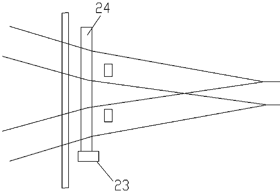
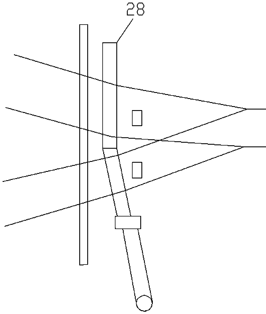
[0002] The rapier loom includes a weft beating part and a weft insertion part. Rigid rapier weft insertion includes single rapier and double rapier weft insertion. Double rapier weft insertion is mainly used for the upper and lower layers of hollow spacer fabrics with relatively large intervals between the upper and lower layers. Weft insertion requires the beating shaft to rotate at a large angle. Since the reed itself is relatively high, in order to prevent the upper edge of the reed from touching the heald frame or heald and at the same time effectively use the opening, a V-shaped reed must be used (see attached image 3 No. 28), and the V-shaped reed is V-shaped, the production process is more complicated, the cycle is long, and the cost is high. When changing the variety, it is difficult for users to afford the price of buying reeds.

Method used


Image

  • Parallel beating-up and weft insertion mechanism
  • Parallel beating-up and weft insertion mechanism
  • Parallel beating-up and weft insertion mechanism

Examples


Embodiment Construction

[0017] Further description will be made below in conjunction with drawings and embodiments.

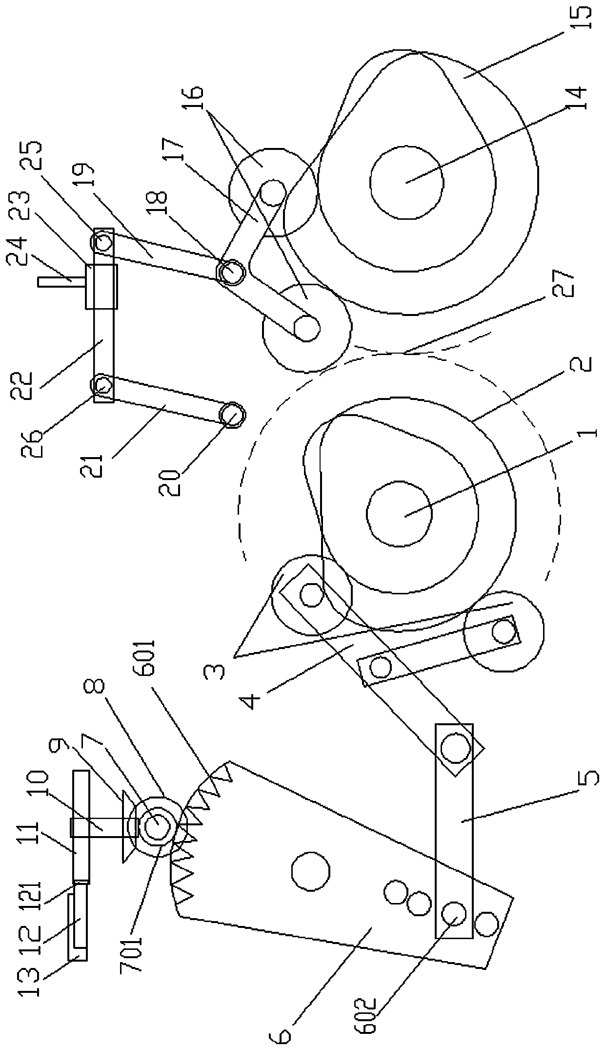
[0018] figure 1 , 2 As shown: a parallel weft beating and weft insertion mechanism includes a weft insertion power shaft 1, a weft insertion conjugate cam group 2, a weft insertion driving rotor 3, a weft insertion swing arm 4, an adjustment connecting rod 5, a weft insertion tooth arm 6, an arc Shaped tooth part 601, pinion shaft 7, tooth part 701, input bevel gear 8, output bevel gear 9, rapier drive shaft 10, rapier drive sprocket 11, rigid rapier 12, strip tooth type 121, rigid rapier Track seat 13, beating power shaft 14, beating conjugate cam group 15, beating drive rotor 16, beating drive swing arm 17, beating drive shaft 18, beating active reed foot 19, beating follower shaft 20 , beat-up follow-up swing arm 21, main follow-up swing arm connecting rod 22, sley 23, steel reed 24.

[0019] The middle part of the weft insertion swing arm 4 is movably hinged on the loom frame ...


PUM


Abstract

The invention relates to a parallel beating-up and weft insertion mechanism. A beating-up driving swing arm is connected to a beating-up driving shaft in a penetrating mode; a beating-up fixed strokereciprocating mechanism drive is connected with the beating-up driving swing arm; a beating-up follow-up shaft and a beating-up driving shaft are respectively connected with the lower end of a beating-up follow-up swing arm and the lower end of a beating-up active reed pin in a penetrating mode; a connecting line of the beating-up driving shaft and the beating-up follow-up shaft, the beating-up active reed, the beating-up follow-up swing arm and a main follow-up swing arm connecting rod constitute a parallelogram; the main follow-up swing arm connecting rod is connected with a reed base with areed in a penetrating mode; a weft insertion fixed stroke reciprocating mechanism drive is connected with the lower end of a weft insertion gear arm via a weft insertion swing arm; an arc gear part on the upper part of the weft insertion gear arm is engaged with a gear part on a gear shaft; and the gear shaft is connected with a rapier fluted disc in a penetrating mode via an input bevel gear anda rapier drive shaft to drive the strip-shaped gear engagement on a rigid rapier in a rigid rapier track base. The mechanism can use fell weft insertion weaving and reed parallel beating-up, therebyeffectively simplifying a reed structure and the manufacturing cycle and cost, and conveniently achieving variety replacement.

Description

technical field [0001] The invention relates to a loom structure, in particular to a parallel beating and weft insertion mechanism. Background technique [0002] The rapier loom includes a weft beating part and a weft insertion part. Rigid rapier weft insertion includes single rapier and double rapier weft insertion. Double rapier weft insertion is mainly used for the upper and lower layers of hollow spacer fabrics with relatively large intervals between the upper and lower layers. Weft insertion requires the beating shaft to rotate at a large angle. Since the reed itself is relatively high, in order to prevent the upper edge of the reed from touching the heald frame or heald and at the same time effectively use the opening, a V-shaped reed must be used (see attached image 3 No. 28), and the V-shaped reed, because the reed teeth are V-shaped, the production process is relatively complicated, the cycle is long, and the cost is high. It is difficult for users to afford the pr...

Claims


Application Information

Patent Timeline
Patent Type & Authority Applications(China)
IPC IPC(8): D03D47/27D03D49/60
CPCD03D47/275D03D49/60
Inventor 王勇
Owner JIANGSU YOUCHENG CNC TECH CO LTD
Learn More