A powerful yarn clearer for a textile machine
A yarn clearer and textile machine technology, applied in textiles and papermaking, fiber cleaning, fiber processing and other directions, can solve the problems of easy-to-damage yarn cleaning effect, etc., and achieve the effect of good cleaning effect and improving cleaning effect.
- Summary
- Abstract
- Description
- Claims
- Application Information
AI Technical Summary
Problems solved by technology
Method used
Image

Examples
Embodiment 1
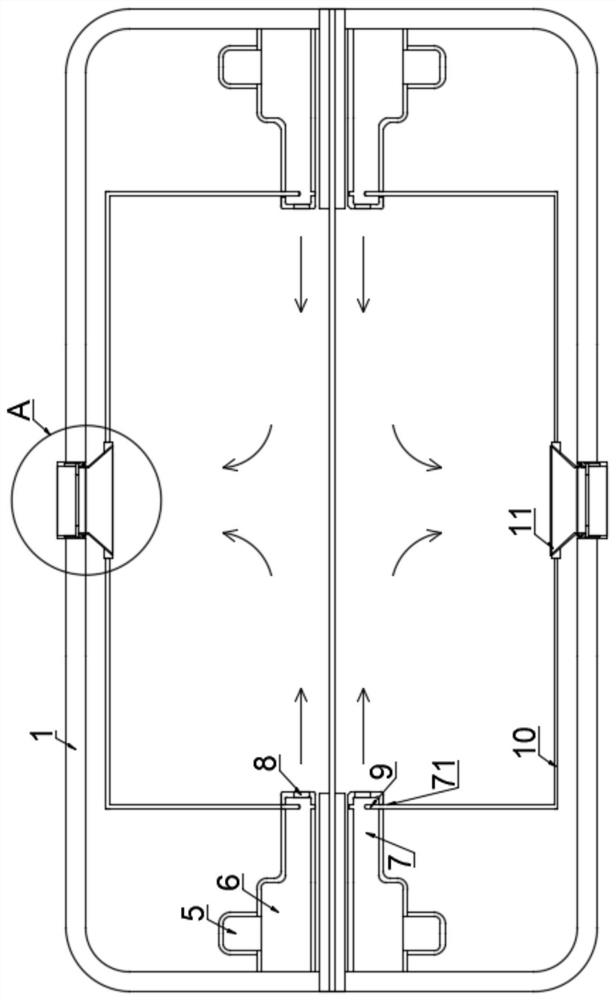
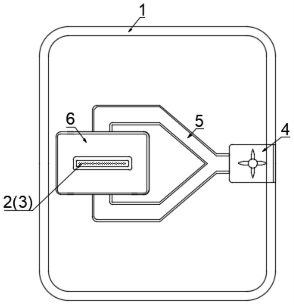
[0030] refer to Figure 1-3 , a powerful yarn clearer for a textile machine, comprising a body 1, the middle part of both sides of the body 1 is connected with a feed pipe 2 and a discharge pipe 3, the feed pipe 2 and the discharge pipe 3 are extended into the body 1, stretched straight A row of yarns enters from the feed pipe 2 and passes through from the discharge pipe 3.
[0031] In the machine body 1, the outer peripheral sides of the feeding pipe 2 and the discharging pipe 3 are equipped with a bellows 6, one side of the bellows 6 is fixedly connected to the inner wall of the body 1, and the upper and lower ends are connected with the same connecting pipe 5, and the connecting pipe 5 is Y-shaped. , two Y-shaped tops are connected to the two ends of the ventilation box 6 and the bottom one is connected to the output end of the fan 4, so that the wind output by the fan 4 to the bellows 6 is evenly distributed in the bellows 6.
[0032] The end of the connecting pipe 5 away...
Embodiment 2
[0046] refer to Figure 4-6 , compared with the first embodiment, the connecting rod 10 is replaced by a first connecting rod 201 , a second connecting rod 202 , and a third connecting rod 203 .
[0047] One end of the first connecting rod 201 is fixedly connected to the air outlet plate 11, the middle part is rotatably connected to the support rod 204 and the other end is rotatably connected to the second connecting rod 202, and the middle part of the second connecting rod 202 is rotatably connected to the support rod 204 and is away from the first connecting rod 201 One end of a connecting rod 201 is provided with a chute 2021 in the axial direction, and the two sides of the chute 2021 are connected with a third connecting rod 203 through a rotating shaft;
[0048] The middle part of the third connecting rod 203 is provided with two spacer rings 18 in clearance fit. Both sides of the two spacer rings 18 are fixedly connected with the same straight bar 19. One end of the straig...
Embodiment 3
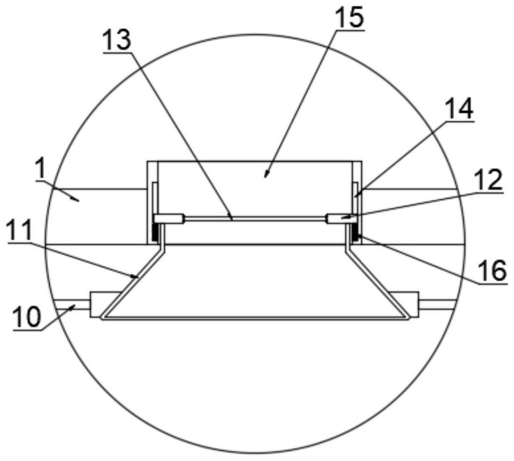
[0053] refer to Figure 7 , Compared with Embodiments 1 and 2, an exhaust fan 21 is installed at the two air outlets 15 on the body 1 .
[0054] Now the principle of embodiment three of the present invention is described as follows:
[0055] An exhaust fan 21 is installed at the two air outlets 15 on the body 1, which is conducive to improving the flow velocity of the gas in the body 1, thereby accelerating the discharge of the gas mixed with impurities after cleaning;
[0056] At the same time, when the opposing winds meet and disperse into the body 1, the scattered airflow is converged and guided to avoid redundant flow in the body 1 and affect the cleaning effect of the subsequent opposing winds.
PUM
 Abstract
Description
Claims
Application Information
 - R&D
- Intellectual Property
- Life Sciences
- Materials
- Tech Scout
- Unparalleled Data Quality
- Higher Quality Content
- 60% Fewer Hallucinations
Browse by: Latest US Patents, China's latest patents, Technical Efficacy Thesaurus, Application Domain, Technology Topic, Popular Technical Reports.
© 2025 PatSnap. All rights reserved.Legal|Privacy policy|Modern Slavery Act Transparency Statement|Sitemap|About US| Contact US: help@patsnap.com