
Shaft aging device

A technology of vibrating devices and clips, which is applied in the field of mechanical processing equipment, can solve the problems of long time, poor aging effect, and can not meet the requirements of better aging effect of shaft parts, etc., and achieve the effect of short time

Pending Publication Date: 2020-03-24
河南德佰特机电设备制造有限公司
View PDF0 Cites 0 Cited by
  • Summary
  • Abstract
  • Description
  • Claims
  • Application Information

AI Technical Summary

Problems solved by technology

[0002] After the initial smelting of metal parts, the force between the molecules in the metal parts is unstable, and the degree of bearing of the metal parts cannot be accurately measured, nor can accurate processing be achieved. As time goes by, the interaction between the molecules in the parts Only when the force reaches a stable state can the degree of bearing of the metal part be accurately measured, the metal part can be better processed into a product, and the product can be installed and used; the force between molecules in the metal part is from an unstable state to a normal state. The aging process of metal parts, this process generally takes more than ten days, depending on the material, sometimes it takes longer
[0003] The equipment used for the aging of metal parts is the aging device for metal parts. The aging device for metal parts includes a base on which a platform is connected with a spring, and a high-frequency vibration device is installed on the platform; in the prior art, there is also There is no special aging device for shaft parts, and the aging device for shaft parts is also used for ordinary metal parts, that is, the shaft parts are placed on the platform, which has the disadvantage of poor aging effect and cannot meet the aging requirements of shaft parts. requirements for better

Method used


Image

  • Shaft aging device
  • Shaft aging device

Examples


Embodiment Construction

[0015] The present invention will be further described below in conjunction with the accompanying drawings.

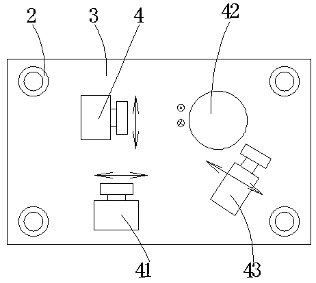
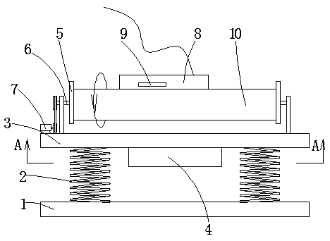
[0016] Such as figure 1 As shown, a shaft aging device includes a base 1, a platform 3 is connected with a spring 2 on the base, and a high-frequency vibration device 4 is installed under the platform; it is characterized in that: The clips 5 at the two shaft ends.

[0017] In the use of the present invention, the two ends of the shaft member 10 can be fixed by the clip, so that the shaft member and the platform are integrated, and the vibration sent by the high-frequency vibrating device 4 can fully act on the shaft member, which can achieve the purpose of the present invention. The vibrating device is a component in the prior art, for example, it can be an electromagnetic vibrating device or a mechanical vibrating device; the clamping part 5 only needs to be able to clamp the two ends of the shaft part 10.

[0018] Further, the clamp 5 is installed on the rotating ...


PUM


Abstract

The invention relates to the technical field of machining equipment, in particular to a shaft aging device. The shaft aging device comprises a base, a platform is connected to the base through a spring, and a high-frequency vibration device is installed below the platform; clamping pieces at the two shaft ends are mounted on the platform; the clamping pieces are installed on the rotating shaft, the lower portion of the rotating shaft is installed on the support, the support is installed on the platform, the rotating shaft is connected with a motor, and the motor rotates to drive the rotating shaft to rotate. The shaft aging device has the advantages of being good in shaft stress eliminating effect and short in time.

Description

technical field [0001] The invention relates to the technical field of machining equipment, in particular to a shaft aging device. Background technique [0002] After the initial smelting of metal parts, the force between the molecules in the metal parts is unstable, and the degree of bearing of the metal parts cannot be accurately measured, nor can accurate processing be achieved. As time goes by, the interaction between the molecules in the parts Only when the force reaches a stable state can the degree of bearing of the metal part be accurately measured, the metal part can be better processed into a product, and the product can be installed and used; the force between molecules in the metal part is from an unstable state to a normal state. The aging process of metal parts generally takes more than ten days, depending on the material, sometimes it takes longer. [0003] The equipment used for the aging of metal parts is the aging device for metal parts. The aging device f...

Claims


Application Information

Patent Timeline
Patent Type & Authority Applications(China)
IPC IPC(8): C21D10/00C22F3/00
CPCC21D10/00C22F3/00
Inventor 吴正龙刘静涛牛欢欢李雪刘世界张正茂
Owner 河南德佰特机电设备制造有限公司
Learn More