Needle warming moxibustion therapeutic instrument for internal medicine
A therapeutic instrument and warm moxibustion technology, applied in the field of internal medicine warm moxibustion therapeutic instrument, can solve the health hazards of medical staff and patients, burns of patients, and the inability to fully exert the efficacy of moxa sticks, etc.
- Summary
- Abstract
- Description
- Claims
- Application Information
AI Technical Summary
Problems solved by technology
Method used
Image
Examples
Embodiment 1
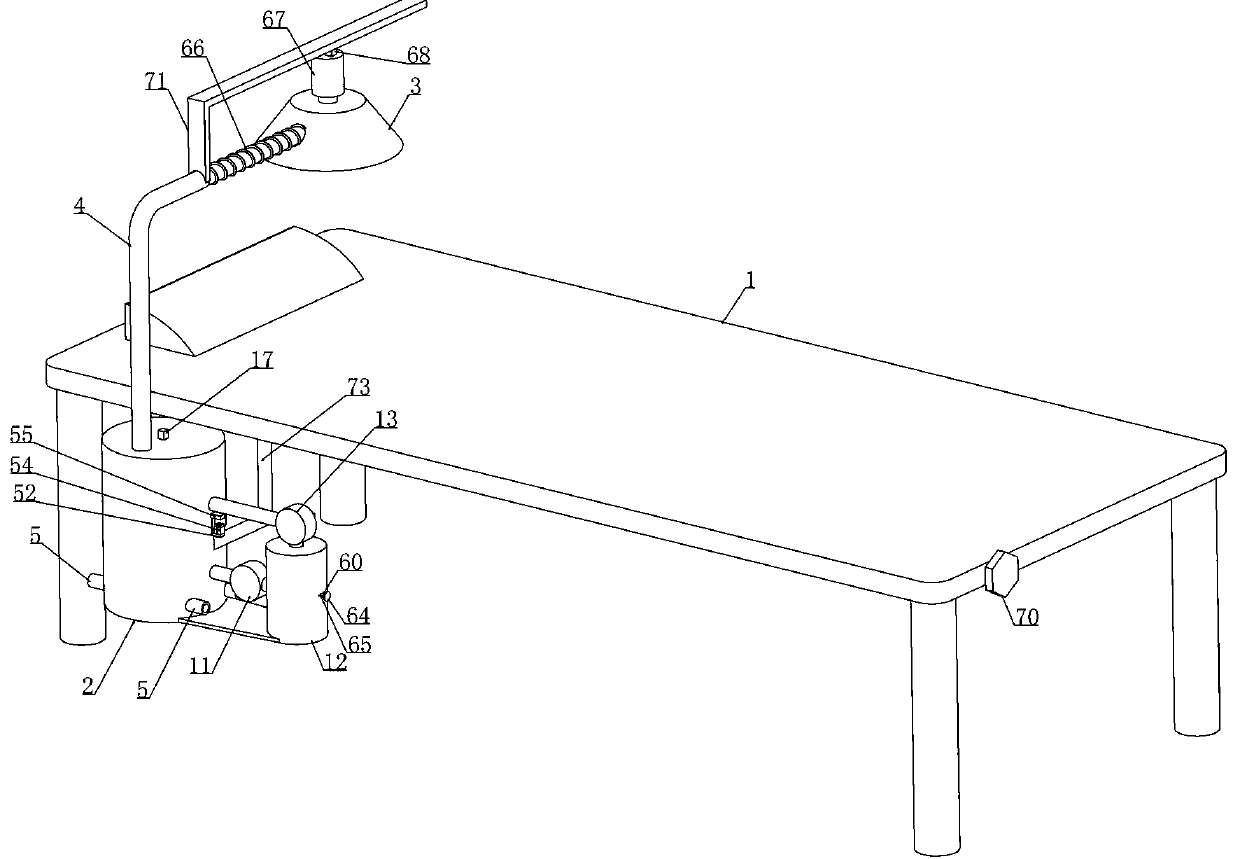
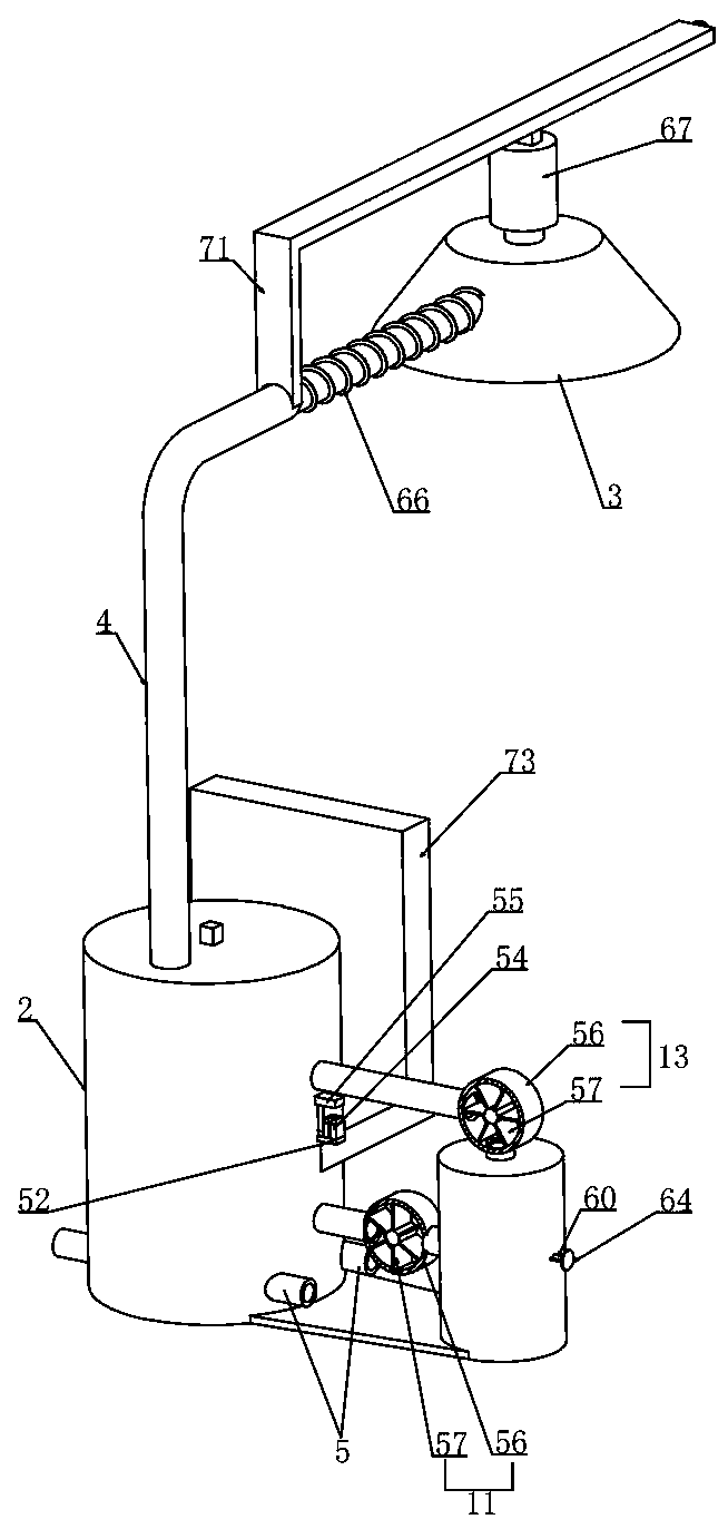
[0045] Embodiment 1, this embodiment provides an internal medicine moxibustion treatment instrument, refer to the attached figure 1 As shown, the bed body 1 is included and the combustion box 2 is installed laterally slidingly on the bed body 1, and the connecting plate 73 is fixedly installed on the outer wall of the combustion box 2, and the connecting plate 73 is horizontally slidingly installed on the lower end surface of the bed body 1. The body 1 is rotatably installed with an adjustment screw 70 that is threadedly matched with the connecting plate 73. By rotating the adjustment screw 70, the combustion box 2 is driven to move laterally along the bed body 1. We connect the combustion box 2 with a moxibustion cover through the conduit 4. 3. The duct 4 is connected to the warm moxibustion cover 3 via a flexible hose 66. The duct 4 is a hard tube and the inner wall of the duct 4 is equipped with a material with a thermal insulation effect, such as phenolic foam, which has lo...
Embodiment 2
[0052] Embodiment 2, on the basis of Embodiment 1, we rotate and install the ring 15 on the inner wall of the combustion box 2, and at the beginning, the positioning device realizes the positioning effect of the ring 15, referring to the attached Figure 16 As shown, the bottom of the circular cavity 14 is rotated with the drive plate 78 coaxially. The output shaft of the rotating motor 17 passes through the circular cavity 14 and drives several striking devices. When the temperature in 3 was lower than the required range, the micro-control processor controlled the operation of the rotating motor 17, referring to the attached Figure 17 As shown, the output shaft of the rotating motor 17 is driven by the rotating motor 17 along the Figure 17 Rotate in the clockwise direction shown in , when the second driving rod 29 is not in conflict with the first driving rod 28, the rotating motor 17 first drives the striking device to knock the filter cover 9, thereby pushing the filter c...
Embodiment 3
[0057] Embodiment 3, on the basis of embodiment 1, with reference to appended Figure 13 As shown, the rotating motor 17 starts to drive some second bevel gears 31 to rotate through the first bevel gear 30 sleeved on its output shaft, and some of the second bevel gears 31 are rotated and installed directly above the center of the filter cover 9 On the support plate 32, the second bevel gear 31 transmits the driving force to the beating device through the universal transmission device and realizes the effect of driving the beveling device to beat and knock the filter cover 9, refer to the attached Figure 13 As shown, the universal transmission device includes a connecting shaft 41 that rotates coaxially with the second bevel gear 31 and a universal joint 42 is connected between the connecting shaft 41 and the striking device, and the universal joint 42 can realize universal transmission. Furthermore, the driving force of the second bevel gear 31 is transmitted to the striking ...
PUM
 Abstract
Description
Claims
Application Information
 - R&D Engineer
- R&D Manager
- IP Professional
- Industry Leading Data Capabilities
- Powerful AI technology
- Patent DNA Extraction
Browse by: Latest US Patents, China's latest patents, Technical Efficacy Thesaurus, Application Domain, Technology Topic, Popular Technical Reports.
© 2024 PatSnap. All rights reserved.Legal|Privacy policy|Modern Slavery Act Transparency Statement|Sitemap|About US| Contact US: help@patsnap.com


