Eureka AIR delivers breakthrough ideas for toughest innovation challenges, trusted by R&D personnel around the world.

Gas-liquid two-phase flow heat insulation shield pump in air conditioner refrigeration cycle system

A gas-liquid two-phase flow and circulation system technology, applied in refrigeration and liquefaction, cooling fluid circulation devices, refrigerators, etc., can solve the problems of inability to completely eliminate gas-liquid mixed state, centrifugal pump impeller impact, high maintenance costs, etc.

Active Publication Date: 2020-03-20
乐清市泰博恒电子科技有限公司
View PDF8 Cites 5 Cited by
  • Summary
  • Abstract
  • Description
  • Claims
  • Application Information

AI Technical Summary

Problems solved by technology

[0003] When the gas-liquid mixture medium is pumped by the centrifugal pump, it will cause a large impact on the impeller of the centrifugal pump, and it is messy, the frequency of impeller damage is high, the maintenance cycle is short, and the maintenance cost is high
[0004] And by changing the position of the pump so that it is far away from the vaporization point of the medium, there is also the problem that the gas-liquid mixed state cannot be completely eliminated, because according to the gas-liquid equilibrium conditions of the substance, there are always gaseous substances under different pressures. When filling Freon , there is also some insoluble protective gas mixed into the coolant to follow the refrigeration cycle

Method used


Image

  • Gas-liquid two-phase flow heat insulation shield pump in air conditioner refrigeration cycle system
  • Gas-liquid two-phase flow heat insulation shield pump in air conditioner refrigeration cycle system
  • Gas-liquid two-phase flow heat insulation shield pump in air conditioner refrigeration cycle system

Examples


Embodiment Construction

[0026] The following will clearly and completely describe the technical solutions in the embodiments of the present invention with reference to the accompanying drawings in the embodiments of the present invention. Obviously, the described embodiments are only some, not all, embodiments of the present invention. Based on the embodiments of the present invention, all other embodiments obtained by persons of ordinary skill in the art without making creative efforts belong to the protection scope of the present invention.

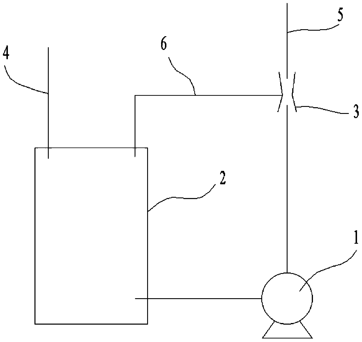
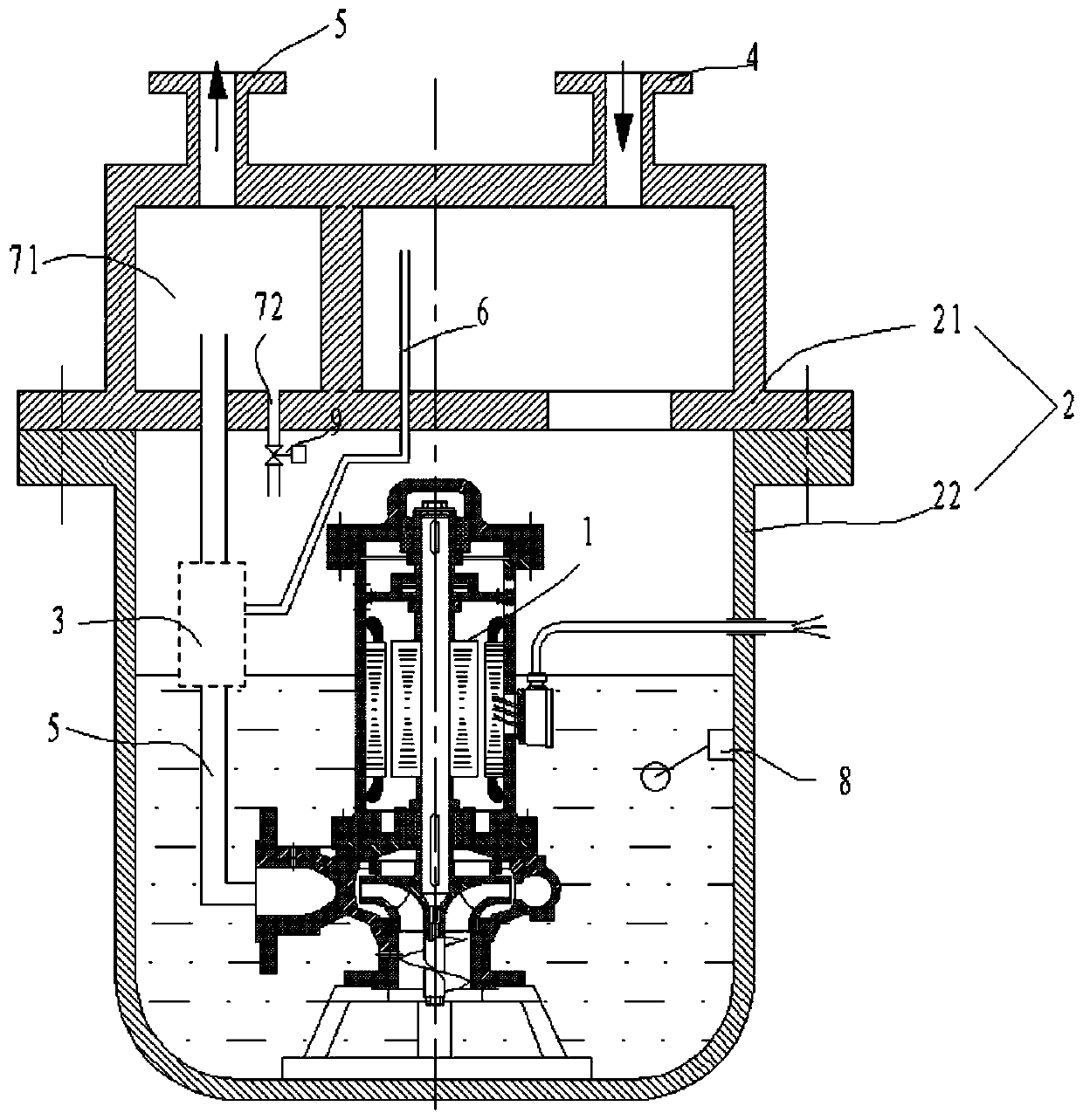
[0027] Such as figure 1As shown, the gas-liquid two-phase flow adiabatic shielded pump in the air-conditioning refrigeration cycle system includes the main pump 1, the separation tank 2, the air extraction assembly 3, the inlet pipe 4, the outlet pipe 5 and the air induction pipe 6, and the inlet of the main pump 1 is connected separately. At the bottom of the tank 2, the outlet of the main pump 1 is connected to the outlet pipe 5, the outlet pipe 5 is provide...


PUM


Abstract

The invention discloses a gas-liquid two-phase flow heat insulation shield pump in an air conditioner refrigeration cycle system. The pump comprises a main pump, a separation tank, an air exhaust assembly, an inlet pipe, an outlet pipe and an air entraining pipe. An inlet of the main pump is connected with the bottom of the separation tank, an outlet of the main pump is connected with the outlet pipe, the air exhaust assembly is arranged on the outlet pipe, one end of the air entraining pipe is connected with the air exhaust assembly, and the other end of the air entraining pipe is connected with the top of the separation tank. The air exhaust assembly comprises a branch pipe, a first venturi pipe, a second venturi pipe and a pressure regulating valve. The first venturi tube is arranged onthe outlet pipe; one end of a parallel pipeline of the branch pipe serving as the outlet pipe is connected to the throat of the first venturi pipe, the other end of the parallel pipeline is connectedwith the inlet end of the first venturi pipe, the second venturi pipe and the pressure regulating valve are arranged on the branch pipe, the pressure regulating valve is closer to the main pump thanthe second venturi pipe, and the throat of the second venturi pipe is connected with an air entraining pipe.

Description

technical field [0001] The invention relates to the field of gas-liquid delivery pumps, in particular to a gas-liquid two-phase flow adiabatic shield pump in an air-conditioning refrigeration cycle system. Background technique [0002] In the air-conditioning and refrigeration cycle system, there is liquid mixed material transport, and the general centrifugal pump often chooses impeller resistance or modifies the use position of the pump on the flow path when dealing with it. Freon is a commonly used coolant, which is widely used in air conditioners as a refrigerant for recycling. [0003] When the gas-liquid mixture medium is pumped by the centrifugal pump, it will cause a large impact on the impeller of the centrifugal pump, and it is messy, the frequency of impeller damage is high, the maintenance cycle is short, and the maintenance cost is high. [0004] And by changing the position of the pump so that it is far away from the vaporization point of the medium, there is a...

Claims


Application Information

Patent Timeline
IPC IPC(8): F25B43/00F25B43/04F04D29/66F04D29/22
CPCF04D29/669F04D29/225F04F5/04F25D17/02
Inventor 王锦杰
Owner 乐清市泰博恒电子科技有限公司
Why Eureka
Eureka Blog
Learn More