
Lifesaving ball

A lifesaving ball and shell technology, which is applied in the field of lifesaving balls, can solve the problems of no guarantee of safety, danger, and inability to provide effective protection, and achieve the effect of preventing fluid leakage and accidental touch

Pending Publication Date: 2020-03-20
林延东
View PDF0 Cites 1 Cited by
  • Summary
  • Abstract
  • Description
  • Claims
  • Application Information

AI Technical Summary

Problems solved by technology

[0002] The usual water lifesaving equipment is mostly life jackets, lifebuoys, and foam buoys, which are relatively large in size and are generally only used when swimming, so it is inconvenient to carry them with you.
There are self-inflating wrist-type lifesaving equipment on the market. Although it has certain practicality and portability, it is dangerous because it uses high-pressure bottled liquid gas as the gas source, and its appearance is not small enough. It can be worn while swimming, and the price is relatively expensive. Not many people buy and use it, and it cannot protect the crowd anytime and anywhere.
There are also various technologies that generate gas through chemical reactions to automatically inflate the airbags. Because of their obvious defects, they are either bulky and simple in appearance, or the airbags are easy to break, and their safety is not guaranteed, or they contain toxic and harmful substances that are not healthy and environmentally friendly. unable to provide effective protection

Method used


Image

  • Lifesaving ball
  • Lifesaving ball
  • Lifesaving ball

Examples


Embodiment Construction

[0050] In order to make the technical problems, technical solutions and beneficial effects to be solved by the present invention clearer and clearer, the present invention will be further described in detail below in conjunction with the accompanying drawings and embodiments.

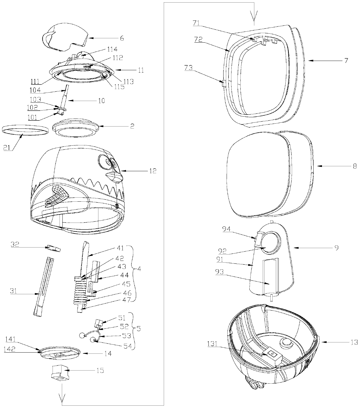
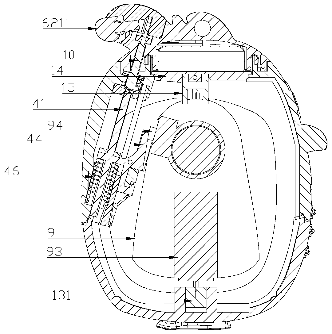
[0051] Such as Figure 1~6 and Figure 9 As shown, this embodiment includes a bottle body, a partition plate 7, a stirring paddle 9, a striker assembly 4, a rope buckle 5, a rotating shaft 10, an elastic air bag 2, an inner cover 14, and a starting device 6;

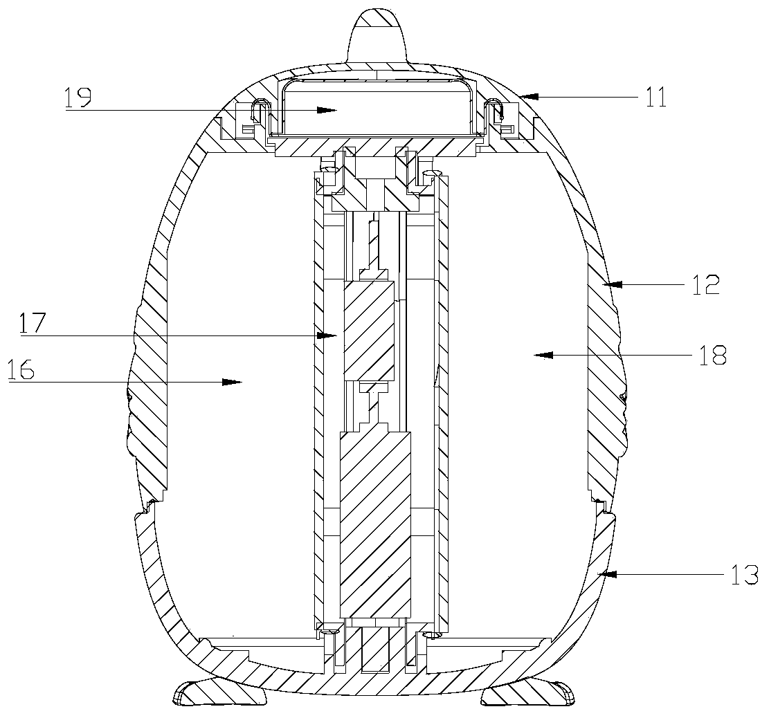
[0052] The bottle body includes a top cover 11, an upper shell 12 and a lower shell 13 assembled sequentially from top to bottom;

[0053] The inner cover 14 is sealed and connected in the bottle mouth of the upper casing 12; the bottle mouth of the upper casing 12 has a height, and the bottle mouth and the upper surface of the inner cover 14 jointly form an airbag chamber 19, the The elastic airbag 2 is sleeved on the bottle mouth of the upper ...


PUM


Abstract

A lifesaving ball relates to the field of water lifesaving appliances. The lifesaving ball comprises a bottle body, a partition plate, stirring blades, a firing pin assembly, a rope buckle, a rotatingshaft and an elastic air bag. The elastic air bag is arranged on the bottle opening; the two groups of partition plates divide the interior of the bottle body into a left bin, a right bin and a middle working bin, and the left bin and the right bin are filled with foaming forming materials; the stirring blade and the striker assembly are arranged in the middle working bin, and the striker assembly is in trigger connection with a power switch of the stirring blade; the rope buckle is connected with the firing pin assembly and the elastic separation membrane. The striker assembly is provided with a striker and a pressing spring; the upper portion of the rotating shaft is connected with the top cover, the lower portion of the rotating shaft is rotatably clamped with the bottle body, and thebottom end of the rotating shaft abuts against the striker to compress the pressing spring. When the rotating shaft rotates and is not clamped with the upper shell, the striker moves upwards to strikethe rotating shaft, so that the top cover is opened; and the firing pin continuously moves upwards to drive the rope buckle and the elastic separation membrane to be separated from the separation plate and continuously moves upwards to trigger a power switch of the stirring blade to be turned on.

Description

technical field [0001] The invention relates to the field of water lifesaving appliances, in particular to a lifesaving ball. Background technique [0002] The usual water lifesaving equipment is mostly life jackets, life buoys, and foam buoys, which are relatively large in size and are generally only used when swimming, so it is inconvenient to carry them with you. There are self-inflating wrist-type lifesaving equipment on the market. Although it has certain practicality and portability, it is dangerous because it uses high-pressure bottled liquid gas as the gas source, and its appearance is not small enough. It can be worn while swimming, and the price is relatively expensive. There are not many people who buy and use it, and it cannot protect the crowd anytime and anywhere. There are also various technologies that generate gas through chemical reactions to automatically inflate the airbags. Because of their obvious defects, they are either bulky and simple in appearance...

Claims


Application Information

Patent Timeline
Patent Type & Authority Applications(China)
IPC IPC(8): B63C9/135B63C9/18
CPCB63C9/135B63C9/18B63C2009/131
Inventor 林延东
Owner 林延东
Learn More