Ink filling structure for pad printer

A pad printing machine and pad printing technology, applied in printing machines, rotary printing machines, printing and other directions, can solve the problems of fast moving speed of the oil cup, full of concave patterns, uneven ink, etc., to achieve convenient and effective adjustment, smooth moving process Effect

Pending Publication Date: 2020-03-20
深圳市诸脉科技有限公司
View PDF1 Cites 0 Cited by
  • Summary
  • Abstract
  • Description
  • Claims
  • Application Information

AI Technical Summary

Problems solved by technology

What you need to know is that the extension and retraction of the piston rod of the cylinder are almost instantaneous actions, which makes the movement speed of the oil cup on the surface of the pad printing steel plate fast and difficult to control, and it is very easy to cause the ink to not be evenly filled with the concave pattern. Especially in the case of large debossed patterns, which in turn leads to poor final embossing effect

Method used


Image

  • Ink filling structure for pad printer
  • Ink filling structure for pad printer

Examples


Embodiment Construction

[0024] In order to have a clearer understanding of the technical features, purposes and effects of the present invention, the specific implementation manners of the present invention will now be described in detail with reference to the accompanying drawings. Apparently, the described embodiments are only some of the embodiments of the present invention, but not all of them. Based on the embodiments of the present invention, all other embodiments obtained by persons of ordinary skill in the art without creative efforts fall within the protection scope of the present invention.

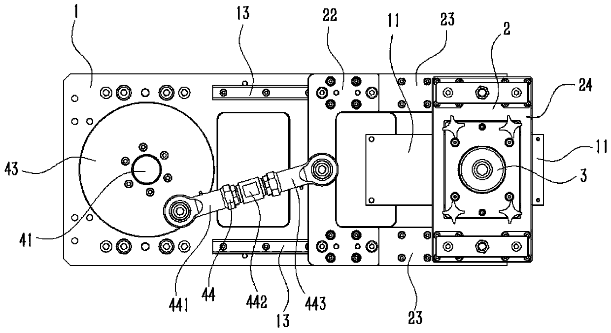
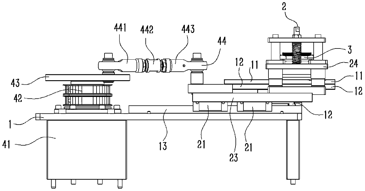
[0025] This embodiment provides an ink filling structure for pad printing machines, especially suitable for ink cup 3 type pad printing machines. The moving speed of the oil cup 3 is more gentle and easier to control, which can ensure that the ink in the oil cup 3 The concave pattern on the pad printing steel plate 11 can be filled evenly.

[0026] The ink filling structure includes a base plate 1, a ...


PUM


Abstract

The invention discloses an ink filling structure for a pad printer. The ink filling structure comprises a substrate, a pad printing steel plate which is fixed to the upper side of the substrate, and the upper surface of the pad printing steel plate is provided with concave patterns; a moving seat is mounted on the substrate in a sliding manner; an ink cup which is mounted on the moving seat and makes contact with the upper surface of the pad printing steel plate; and a driving assembly which is provided with a motor, a first transmission part connected with an output shaft of the motor, and asecond transmission part of which the two opposite ends are rotationally connected with the first transmission part and the moving seat respectively. The motor drives the first transmission part to rotate on a plane parallel to the pad printing steel plate, and in the rotating process of the first transmission part, acting force with periodically changed direction and magnitude is applied to the moving seat through the second transmission part so that the moving seat can reciprocate on the base plate. The moving speed of the ink cup of the ink filling structure is gentler and easier to control, and it can be guaranteed that ink in the ink cup can be evenly filled into the concave patterns on the pad printing steel plate.

Description

technical field [0001] The invention relates to the field of ink printing equipment, in particular to an ink filling structure for a pad printing machine. Background technique [0002] The working principle of the oil cup pad printing machine is: the oil cup filled with ink moves back and forth in a straight line on the surface of the pad printing steel plate, and the ink in the oil cup fills in the concave pattern on the surface of the pad printing steel plate during the movement; The pad printing rubber head moves vertically downwards to pick up the ink filled in the concave pattern, and then translates to the top of the workpiece table where the printing workpiece is placed in advance, and then moves downwards to stick the ink on the surface of the pad printing rubber head. The ink forming the concave pattern is imprinted on the surface of the printing workpiece to complete the pad printing process. The current problem is that in the existing oil cup pad printing machine...

Claims


Application Information

Patent Timeline
IPC IPC(8): B41F17/00B41F31/00
CPCB41F17/001B41F31/00
Inventor 莫勇黄仕波
Owner 深圳市诸脉科技有限公司
Why Eureka
Try Eureka