Gang drilling machine for aluminum alloy plate machining

An aluminum alloy plate and drilling rig technology, which is used in metal processing machinery parts, metal processing, metal processing equipment, etc. Problems such as single working mode, to achieve the effect of easy feeding and transportation, easy collection, and reduced resistance

Active Publication Date: 2020-03-20
安徽佐小柱企业管理咨询有限公司
View PDF10 Cites 0 Cited by
  • Summary
  • Abstract
  • Description
  • Claims
  • Application Information

AI Technical Summary

Problems solved by technology

[0002] In the manufacturing process of aluminum alloy plate products, it is necessary to drill holes at the specified size and position of the plate according to the product design requirements. In most existing factories, most of the holes are arranged manually through manual drilling, and some factories use full drilling. The manually controlled drilling machine drills the plate. During the drilling process, it needs to be limited by the size limit bar on the machine and then drilled. This method is cumbersome during the work process, and the drilling The position is prone to shift and the accuracy is poor
In addition, the working mode of the row drilling machine in the prior art is relatively simple, and can only be processed according to the specified hole, and the drill bit needs to be replaced when processing different apertures, and the work efficiency is slow.
Most of the row drilling rigs are not equipped with rotary row drilling, and it is impossible to perform alternate work of row drilling and single drilling
In addition, the waste chips produced by the row drilling machine in the prior art are difficult to handle and cannot be collected well.

Method used


Image

  • Gang drilling machine for aluminum alloy plate machining
  • Gang drilling machine for aluminum alloy plate machining
  • Gang drilling machine for aluminum alloy plate machining

Examples


Embodiment Construction

[0031] The following will clearly and completely describe the technical solutions in the embodiments of the present invention with reference to the accompanying drawings in the embodiments of the present invention. Obviously, the described embodiments are only some, not all, embodiments of the present invention. Based on the embodiments of the present invention, all other embodiments obtained by persons of ordinary skill in the art without making creative efforts belong to the protection scope of the present invention.

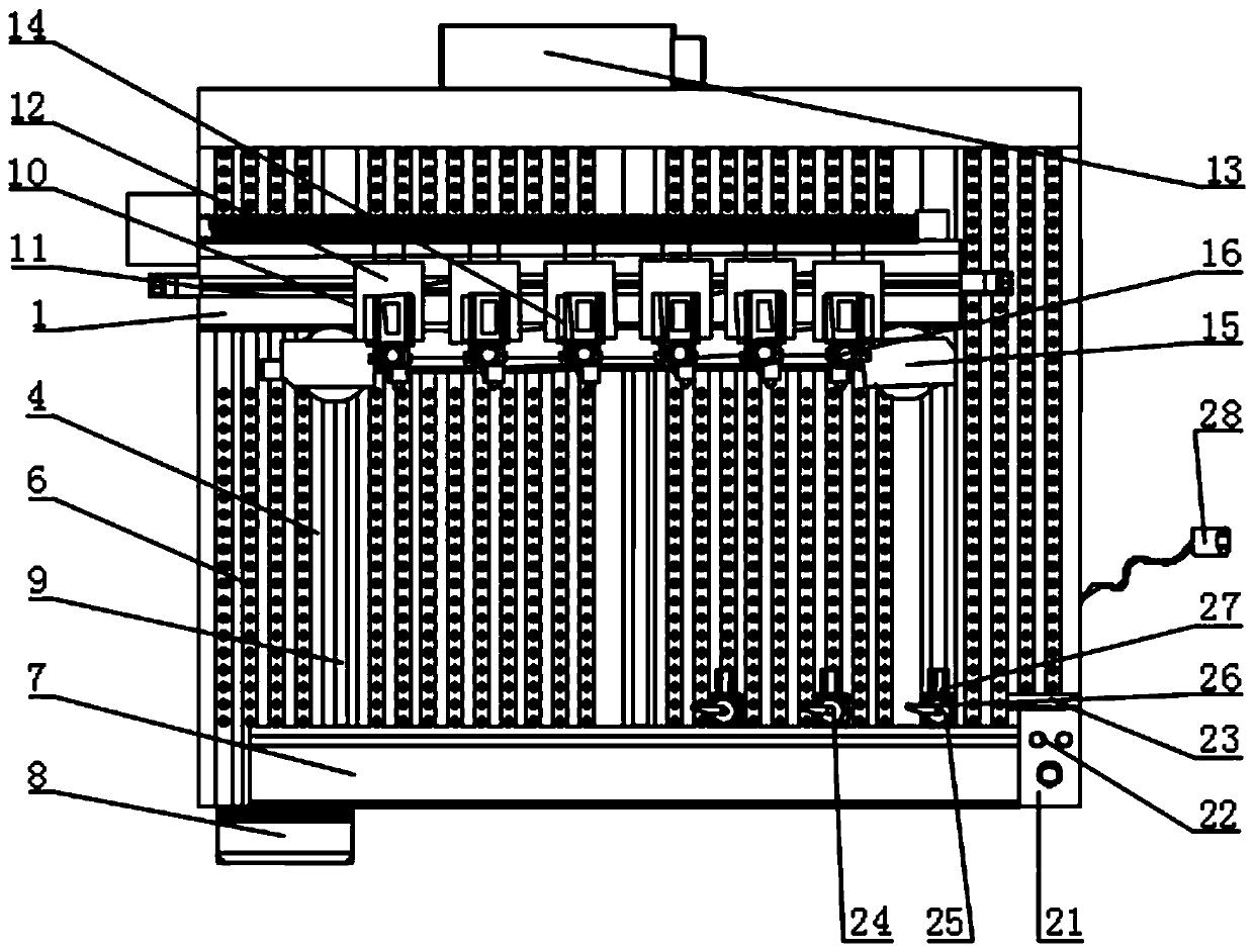
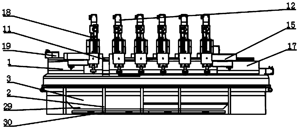
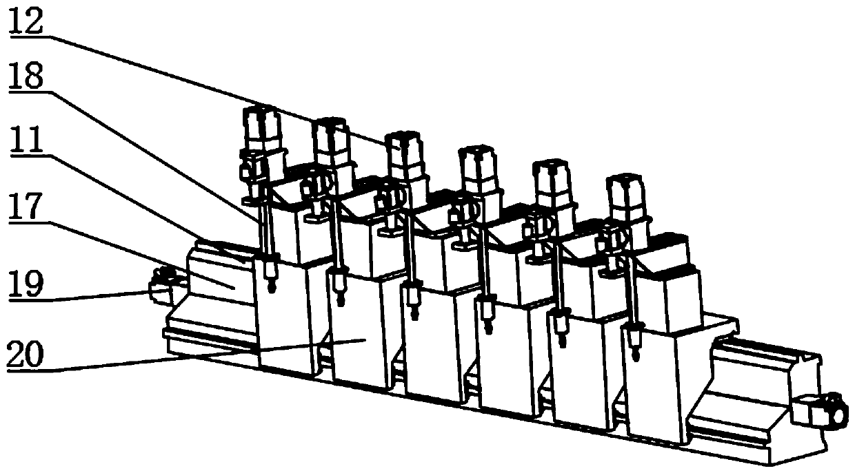
[0032] see Figure 1-7, the present invention provides a row drilling machine for aluminum alloy plate processing: comprising a device main body 1, a support frame 2 and a base 3 are fixedly installed on the bottom of the device main body 1, and a workbench 4 is provided on the upper end of the base 3, A crossbeam connecting rod 5 is fixedly connected to the worktable 4, a ball 6 is installed on the upper end of the crossbeam connecting rod 5, and an X-axis dr...


PUM


Abstract

The invention relates to the technical field of crushers, and particularly relates to a gang drilling machine for aluminum alloy plate machining, which comprises a device main body. A support frame and a base are fixedly mounted at the bottom of the device main body; a workbench is arranged at the upper side end of the base; a ball is mounted at the upper end of a cross beam connecting rod; an X-axis driving body is mounted on one side of the workbench; a servo driving motor is mounted on one side of the X-axis driving body; a gang drill main body is mounted on one side of the Z-axis driving body; a Z-axis cylinder is mounted in the Z-axis driving body; the servo motor is integrally controlled by the servo system to operate to accurately control the drilling precision of the plate; the gang drill is integrally drilled through six sets of single drill bodies. In addition, the rotary discs on the two sides are matched to drive the drill bits of multiple specifications to conduct drilling, the specification of the hole diameter can be increased, the defect that in a traditional mode, the drill bits are replaced many times is overcome, overall two-shaft feeding is adopted, vertical drilling is matched, and the overall working efficiency is higher than that of a gang drill in the traditional mode.

Description

technical field [0001] The invention relates to the technical field of plate processing equipment, in particular to a row drilling machine for aluminum alloy plate processing. Background technique [0002] In the manufacturing process of aluminum alloy plate products, it is necessary to drill holes at the specified size and position of the plate according to the product design requirements. In most existing factories, most of the holes are arranged manually through manual drilling, and some factories use full drilling. The manually controlled drilling machine drills the plate. During the drilling process, it needs to be limited by the size limit bar on the machine and then drilled. This method is cumbersome during the work process, and the drilling The position is prone to shift and the accuracy is poor. In addition, the working mode of the row drilling rig in the prior art is relatively single, and can only be processed according to the specified holes. When processing dif...

Claims


Application Information

Patent Timeline
Patent Type & Authority Applications(China)
IPC IPC(8): B23B41/00B23Q3/08B23Q7/00B23Q11/00
CPCB23B41/00B23Q3/062B23Q3/08B23Q7/00B23Q11/0046B23Q11/0067B23Q2703/04
Inventor 卢道奎
Owner 安徽佐小柱企业管理咨询有限公司
Why Eureka
Try Eureka