


Quick Research
Generate reliable direction feasibility study reports for your R&D in just a few steps.

Technical Q&A
Discover and master advanced knowledge NOW. Basics, ideas, possibilities, all at once.

Find Solutions
As an expert in R&D theories, this can generate solutions to your technical problems instantly.

Evaluate Feasibility
Analyze your overall solution with one click, know your potential R&D risks in advance.

Monitor Landscape
Get weekly tech updates, stay abreast of the latest tech innovations and key insights.
Angles for ultrasound-based shear wave imaging
A technology of shear wave and ultrasound, which is applied in ultrasonic/sonic/infrasonic diagnosis, ultrasonic/sonic/infrasonic equipment control, sound wave diagnosis, etc. It can solve the problems of inaccuracy and time-consuming
- Summary
- Abstract
- Description
- Claims
- Application Information
AI Technical Summary
Problems solved by technology
Method used
Image


Examples
Embodiment Construction
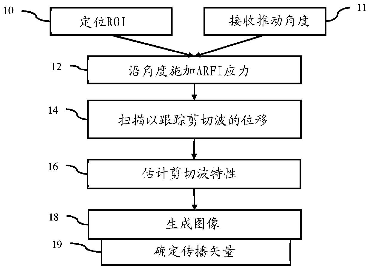
[0013] Provides shear wave vector imaging. Tissue anisotropy causes shear waves to propagate mainly in preferential directions. Addressing anisotropy can improve shear wave elastography (SWEI) and provide additional clinical benefits. In many ultrasound systems, it is difficult to assess anisotropy because the angles of the push and track beams in SWEI are not under user control. Shear wave vector imaging uses vectors for propelling the beam and / or for detected shear wave propagation.
[0014] Shear wave vector imaging can use the angle at which the beam is pushed to better handle anisotropy. In conventional SWEI, the angle at which the beam is pushed is not controlled, but instead is perpendicular to the transducer. The angle of the push beam is selected using user controls or image processing and is controlled independently of the region of interest. By pushing the beam angle through user or automatic control, the resulting estimate of the shear wave properties may be mo...
PUM
 Abstract
Description
Claims
Application Information
 - R&D Engineer
- R&D Manager
- IP Professional
- Industry Leading Data Capabilities
- Powerful AI technology
- Patent DNA Extraction
Browse by: Latest US Patents, China's latest patents, Technical Efficacy Thesaurus, Application Domain, Technology Topic, Popular Technical Reports.
© 2024 PatSnap. All rights reserved.Legal|Privacy policy|Modern Slavery Act Transparency Statement|Sitemap|About US| Contact US: help@patsnap.com