
Machine tool thermal error prediction method and system based on temperature sensitive interval segmentation

A prediction method and thermal error technology, applied in the field of predicting the thermal error of machine tools, can solve problems such as fluctuations in prediction performance, and achieve the effects of strong versatility, improved prediction robustness, and improved prediction accuracy.

Pending Publication Date: 2020-03-17
CHONGQING UNIV OF TECH
View PDF5 Cites 2 Cited by
  • Summary
  • Abstract
  • Description
  • Claims
  • Application Information

AI Technical Summary

Problems solved by technology

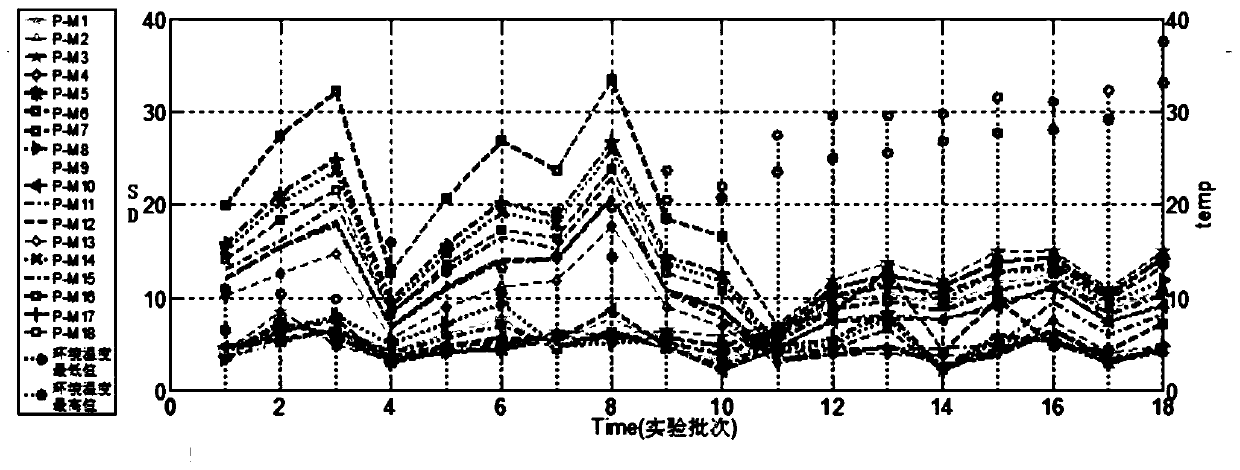
[0008] Aiming at the deficiencies of the above-mentioned prior art, the present invention provides a thermal error prediction method for machine tools based on temperature-sensitive interval segmentation, which solves the prediction performance of the thermal error compensation prediction model of machine tools with strong coupling temperature field due to the influence of ambient temperature Fluctuation problems, greatly improving the prediction accuracy and robustness of the model

Method used


Image

  • Machine tool thermal error prediction method and system based on temperature sensitive interval segmentation
  • Machine tool thermal error prediction method and system based on temperature sensitive interval segmentation
  • Machine tool thermal error prediction method and system based on temperature sensitive interval segmentation

Examples


Embodiment Construction

[0035] The present invention will be further described in detail below in conjunction with the accompanying drawings and preferred embodiments.

[0036] The overall process reference of this specific implementation figure 1 as shown, figure 1 The first four steps in are the specific refinement process for obtaining the temperature sensitive range. Each part is described in detail below.

[0037] 1. Data collection

[0038] The data acquisition system includes an infrared thermal imager, a temperature sensor group and an eddy current displacement sensor;

[0039] Infrared thermal imager is used to make a thermal image of the machine tool to obtain the temperature color image characteristics of the machine tool; according to the temperature color image characteristics displayed by the thermal imager, the heat source area of ​​the machine tool can be manually marked;

[0040]The temperature sensor group is set separately at the heat source area of ​​the manual marking machine...


PUM


Abstract

The invention discloses a machine tool thermal error prediction method and system based on temperature sensitive interval segmentation. The machine tool thermal error prediction method comprises the steps: obtaining a temperature sensitive interval which is an environment temperature interval capable of causing the fluctuation of the prediction performance of a machine tool thermal error, and obtaining the temperature sensitive interval through the prediction of a residual standard deviation change trend graph; selecting temperature sensitive interval segmentation points in the temperature sensitive interval; respectively establishing corresponding machine tool thermal error prediction models on the two sides of the temperature sensitive interval segmentation points by adopting a segmentation modeling method, so as to obtain machine tool thermal error compensation segmentation prediction models; and predicting the thermal deformation of the machine tool by adopting the machine tool thermal error compensation segmented prediction model. The machine tool thermal error prediction system comprises a data acquisition system and a computer, wherein a modeling program and a prediction program are configured in the computer. According to the machine tool thermal error prediction method and system, the problem that the prediction performance of the machine tool thermal error compensation prediction model of the strong coupling temperature field fluctuates due to the influence of the environment temperature is solved, and the prediction precision and the prediction robustness of themodel are greatly improved.

Description

technical field [0001] The invention relates to the technical field of precision machining machine tools, in particular to a method and system for predicting thermal errors of machine tools. Background technique [0002] With the rapid development of precision and ultra-precision machining technology, higher requirements are put forward for the machining accuracy and reliability of CNC machine tools and machining centers. During the actual processing and operation of CNC machine tools, due to the influence of factors such as friction heat, cutting heat and ambient temperature on the process system, the expansion of machine tool parts will cause thermal deformation. This thermal deformation will change the relative position between the various parts of the machine tool, causing the tool to deviate from the ideal cutting point, resulting in a reduction in the machining accuracy of the machine tool, and this error caused by thermal deformation is called thermal error. Thermal ...

Claims


Application Information

Patent Timeline
IPC IPC(8): G06F17/18
CPCG06F17/18Y02P90/30
Inventor 苗恩铭刘昀晟陈阳杨戚玉海
Owner CHONGQING UNIV OF TECH
Learn More