
An experimental test device based on rail transit pantograph-caten current receiving system

A technology of rail transit and testing device, applied in the direction of measuring device, measuring electricity, measuring electrical variables, etc., can solve the problem of difficulty in observation and research of skateboard state, and achieve the effect of adjustable and controllable pressure and speed

Active Publication Date: 2020-09-08
SOUTHWEST JIAOTONG UNIV
View PDF9 Cites 0 Cited by
  • Summary
  • Abstract
  • Description
  • Claims
  • Application Information

AI Technical Summary

Problems solved by technology

However, it is impossible to directly use the removed skateboard configuration in a real pantograph-catenary system for related experiments, and it is also difficult to observe and study the skateboard state during driving.
There is currently no test platform dedicated to pantograph-catenary experiments

Method used


Image

  • An experimental test device based on rail transit pantograph-caten current receiving system
  • An experimental test device based on rail transit pantograph-caten current receiving system
  • An experimental test device based on rail transit pantograph-caten current receiving system

Examples


Embodiment Construction

[0026] The present invention will be further described below in conjunction with the accompanying drawings and specific embodiments.

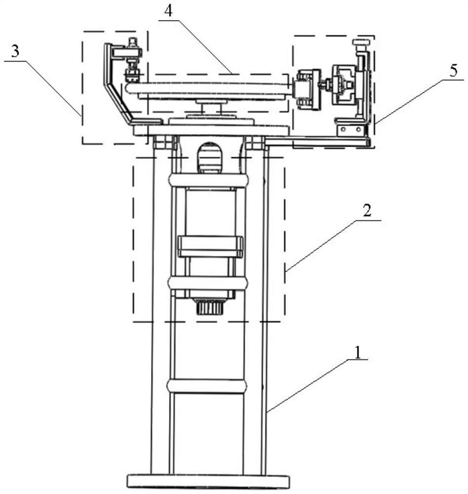
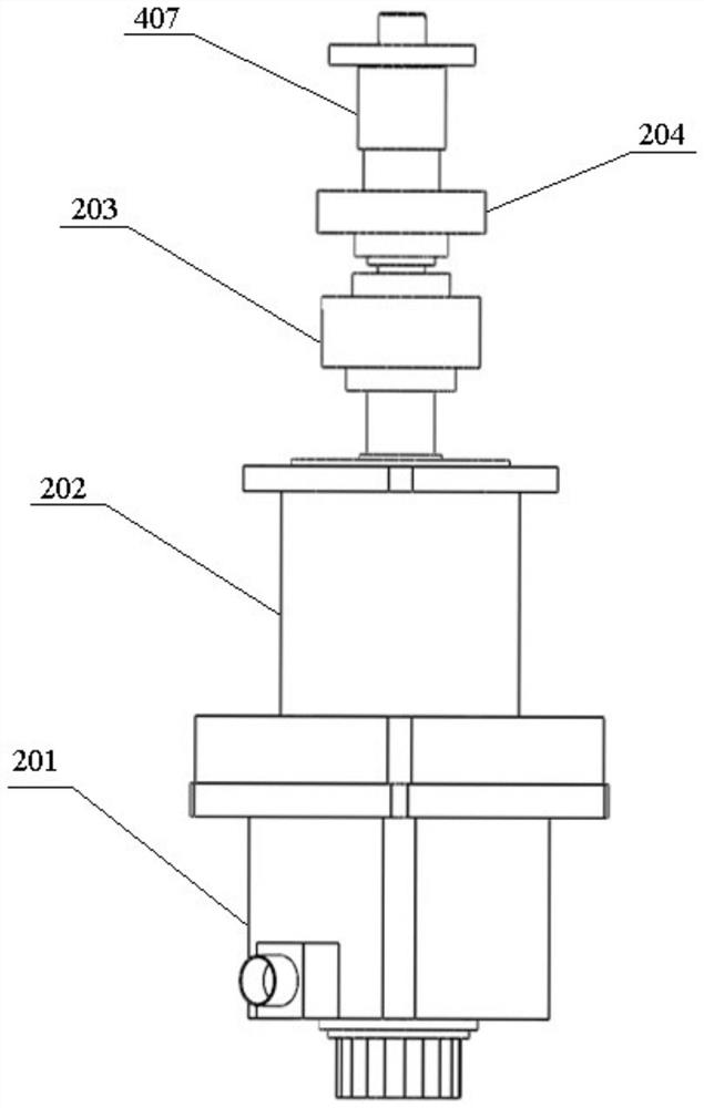
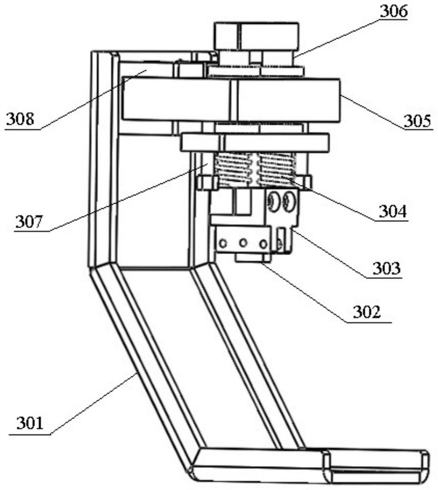
[0027] like Figure 1-7 As shown, an experimental test device based on the rail transit pantograph-catenary current receiving system includes a base 1 and a motor device 2 arranged in the base 1; it also includes a metal turntable 404 arranged above the motor device 2 and driven by the motor device 2 The rotating turntable device 4; the opposite sides of the turntable device 4 are respectively provided with a current-carrying device 3 for supplying power to the metal turntable 404 and a current receiving device 5 for installing a test slide; the test slide in the current receiving device 5 and the metal turntable 404 contact connection.

[0028] The motor device 2 includes a servo motor 201 and a planetary reducer 202 connected to the servo motor 201 shaft; The rotational speed of the servo motor 201 is adjustable, and the rotational speed th...


PUM


Abstract

The invention discloses an experimental test device based on a rail transit pantograph-catenary current receiving system, which includes a base and a motor device arranged in the base; and a turntable device arranged above the motor device and driven by the motor device to rotate its metal turntable; The opposite sides of the turntable device are respectively provided with a current-carrying device for supplying power to the metal turntable and a current-receiving device for installing a test slide; the test slide in the current-receiving device is in contact with the metal turntable; the present invention can be used in relatively stable and safe experiments. The research on the skateboard in the laboratory environment has laid the foundation for improving and perfecting the existing pantograph-catenary system.

Description

technical field [0001] The invention relates to the technical field of experimental testing equipment, in particular to an experimental testing device based on a rail transit pantograph-catenary current receiving system. Background technique [0002] Electric traction locomotives usually use "pantograph-catenary" to contact each other to transmit electric energy. Usually the pantograph is installed on the top of the train carriage and supports a single or multiple carbon slides, while the catenary is suspended above the roof through the towers set along the railway line. During the operation of the electric locomotive, the electric energy of the traction power supply system passes through During the sliding electrical contact process between the catenary and the carbon slide, the electric energy of the traction power supply system is transmitted to the inside of the train through the pantograph through the sliding electrical foundation between the catenary and the carbon sli...

Claims


Application Information

Patent Timeline
Patent Type & Authority Patents(China)
IPC IPC(8): G01R31/00
CPCG01R31/00
Inventor 肖嵩罗远培吴京驰张灿饶阳童梦园李玉航杨泽锋吴广宁
Owner SOUTHWEST JIAOTONG UNIV
Learn More