Working method of belling machine for metal pipe processing
A working method and metal tube technology, applied in the field of flaring machines, can solve the problems of reducing the forming quality of metal tubes, increasing the cost of lubricating fluid, and scratching the surface of metal tubes, so as to improve the forming quality, be easy to take out, and save lubricating fluid. Effect
- Summary
- Abstract
- Description
- Claims
- Application Information
AI Technical Summary
Problems solved by technology
Method used
Image
Examples
Embodiment 1
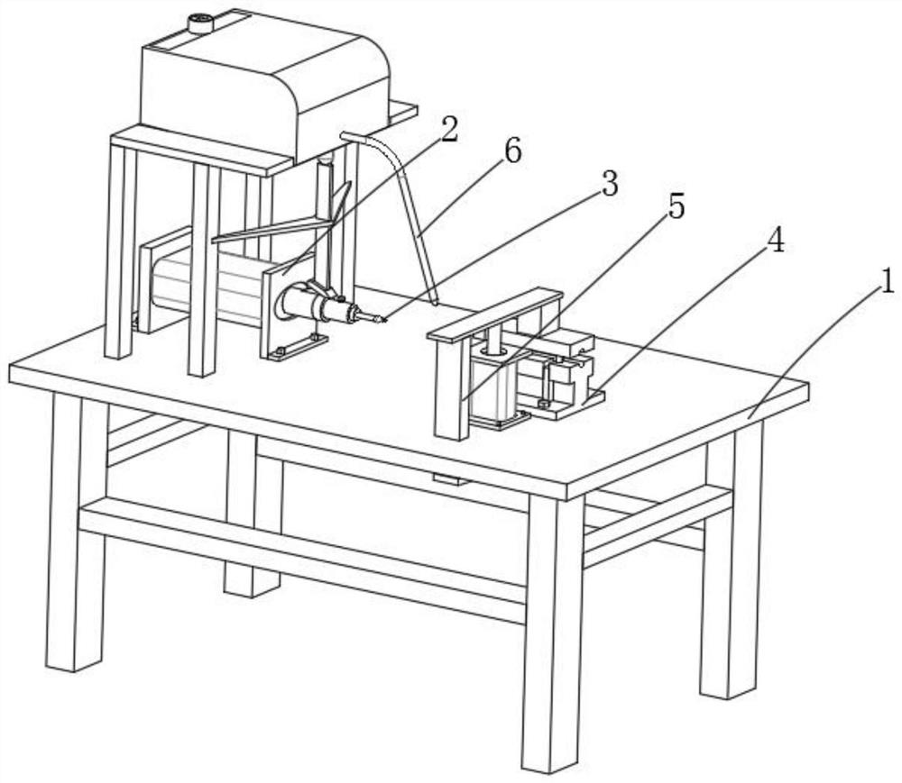
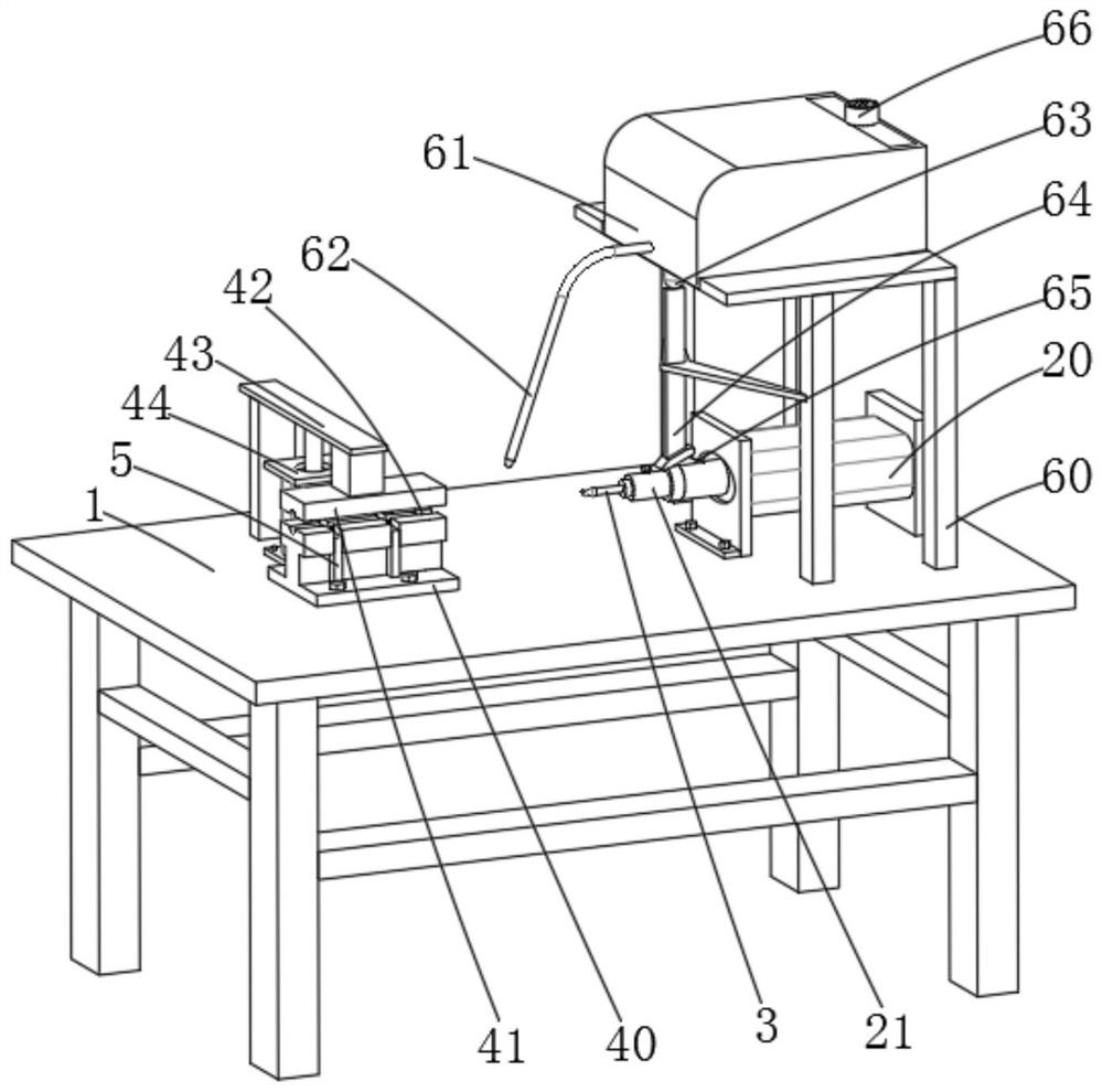
[0028] Example 1, please refer to figure 1 , a metal tube processing belling machine, including a workbench 1, the top of the workbench 1 is provided with a reaming mechanism 2 for metal pipe mouth reaming, the reaming mechanism 2 is provided near the center of the workbench 1 length direction There is a reaming needle 3 for reaming the nozzle. The top of the workbench 1 is provided with a clamping mechanism 4 on the same axis as the reaming needle 3 for clamping the metal pipe. The inside of the clamping mechanism 4 is pierced with a The jacking mechanism 5 is used for unloading metal pipes after reaming.
[0029] Please refer to figure 2 , the reaming mechanism 2 includes a reaming cylinder 20 fixed on the top of the workbench 1, the output end of the reaming cylinder 20 is fixedly connected with a reaming fixture 21, specifically, the reaming fixture 21 is used for clamping the reaming needle 3 .
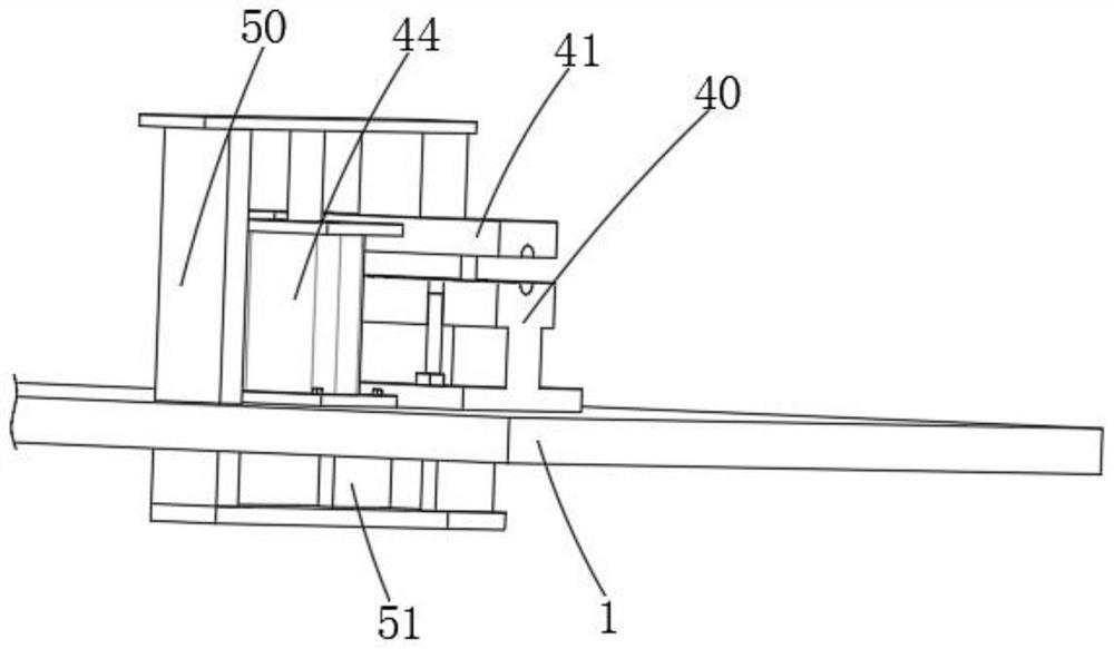
[0030] refer to figure 2 and image 3 , the clamping mechanism 4 incl...
Embodiment 2
[0042] Example 2, please refer to Figure 6 , Figure 7 and Figure 8 , the top of the workbench 1 is provided with a feeding mechanism 7 located on the side of the clamping mechanism 4. The feeding mechanism 7 includes a screw 72 that is rotatably connected to the right side of the lower template 40, and the surface of the screw 72 is covered with a limit plate 70. Specifically , the surface of the screw rod 72 is provided with external threads, the inside of the limiting plate 70 is provided with internal threads that match the external threads, the limiting plate 70 is threadedly connected with the threaded rod, and the limiting plate 70 and the lower template 40 are passed through a slide bar 71 is slidingly connected, and the side of the lower template 40 away from the compression cylinder 44 is provided with a storage frame 77 fixedly connected to the workbench 1, and a loading plate 73 is provided between the storage frame 77 and the limit plate 70. Specifically, the l...
PUM
 Abstract
Description
Claims
Application Information
 - R&D
- Intellectual Property
- Life Sciences
- Materials
- Tech Scout
- Unparalleled Data Quality
- Higher Quality Content
- 60% Fewer Hallucinations
Browse by: Latest US Patents, China's latest patents, Technical Efficacy Thesaurus, Application Domain, Technology Topic, Popular Technical Reports.
© 2025 PatSnap. All rights reserved.Legal|Privacy policy|Modern Slavery Act Transparency Statement|Sitemap|About US| Contact US: help@patsnap.com


