
High-integrity pressure protecting system of LNG receiving station after-gasification outward transmission pipeline

A technology to protect the system and integrity, applied in the pipeline system, gas/liquid distribution and storage, mechanical equipment, etc., can solve the problems of increased investment, increased investment, insufficient safety and reliability, etc., to achieve high safety and reliability, guarantee pressure Safe and effective

Pending Publication Date: 2020-03-13
CNOOC GAS & POWER GRP
View PDF0 Cites 0 Cited by
  • Summary
  • Abstract
  • Description
  • Claims
  • Application Information

AI Technical Summary

Problems solved by technology

[0004] There are three traditional solutions. One is to logically associate the emergency shut-off valve at the first station of the export pipeline with the emergency shut-off valve at the outlet of the gasifier at the LNG receiving station. The emergency shut-off valve at the outlet of the gasifier adopts Quickly close the valve, but there is an unreliability problem in the logical connection of the instrument; the second is to add a safety valve and vent between the emergency shut-off valve at the first station of the export pipeline and the emergency shut-off valve at the outlet of the gasifier, but it is necessary to greatly increase the LNG reception The processing capacity of the station flare system and the investment in the discharge pipeline will increase the investment cost of equipment, and in addition, a larger site safety distance is required; the third is to increase the design pressure of the first station of the export pipeline to the design pressure of the export system of the LNG receiving station Consistent, of course, will also lead to a greater increase in investment
Therefore, there are various drawbacks in traditional solutions, such as insufficient safety and reliability, or a substantial increase in related investment

Method used


Image

  • High-integrity pressure protecting system of LNG receiving station after-gasification outward transmission pipeline

Examples


Embodiment Construction

[0018] It should be understood that the terminology used herein is for the purpose of describing particular example embodiments only and is not intended to be limiting. As used herein, the singular forms "a", "an" and "the" may also be meant to include the plural forms unless the context clearly dictates otherwise. The terms "comprising", "comprising", "containing" and "having" are inclusive and thus indicate the presence of stated features, steps, operations, elements and / or parts but do not exclude the presence or addition of one or Various other features, steps, operations, elements, components, and / or combinations thereof. The method steps, processes, and operations described herein are not to be construed as necessarily requiring their performance in the particular order described or illustrated, unless an order of performance is specifically indicated. It should also be understood that additional or alternative steps may be used.

[0019] Although the terms first, seco...


PUM


Abstract

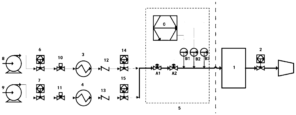
The invention relates to a high-integrity pressure protecting system of an LNG receiving station after-gasification outward transmission pipeline. The system comprises a cut-off valve, a pressure transmitter and a logical processing controller; the cut-off valve and the pressure transmitter are sequentially disposed on a pipeline between a gasifier outward transmission main pipe and an outward transmission pipeline initial station; the logical processing controller is electrically connected with the cut-off valve and the pressure transmitter; and the logical processing controller performs thelogical judgment on a pressure value detected by the pressure transmitter, then the cut-off valve is controlled to perform cutting-off according to a preset pressure alarm value which is lower than the design pressure of the outward transmission pipeline initial station, gas which continuously increases in the gasifier outward transmission main pipe is controlled in a range of the gasifier outwardtransmission main pipe and does not enter the outward transmission pipeline initial station.

Description

technical field [0001] The invention relates to a high-integrity pressure protection system for an export pipeline after gasification at an LNG receiving station, and relates to the technical field of liquefied natural gas (LNG). Background technique [0002] The LNG receiving station is usually built as a supporting or independent construction of the first station of the export pipeline. The function of the first station of the export pipeline is mainly to measure the natural gas transported downstream. It is equipped with a pig launch device, a metering device and a pressure regulating device. Usually, it is economical and feasible to put the first station of the export pipeline within the boundaries of the LNG receiving station or build it independently at a position close to the boundary of the LNG receiving station. The control system of the export pipeline usually interacts with the control system of the LNG receiving station. independent. However, the problem brought...

Claims


Application Information

Patent Timeline
IPC IPC(8): F17D1/00F17D3/01F17D5/00
CPCF17D1/005F17D3/01F17D5/00
Inventor 付子航杨玉霞刘方冯亮杨宏伟黄洁馨韩银杉
Owner CNOOC GAS & POWER GRP
Learn More