Press plate device and application method thereof
A pressing plate and monitoring device technology, which is applied in the field of pressing plate devices, can solve the problems of not being suitable for double-sided engraving, and achieve the effects of improving engraving efficiency and quality, improving the quality of finished products, and being convenient to use
- Summary
- Abstract
- Description
- Claims
- Application Information
AI Technical Summary
Problems solved by technology
Method used
Image
Examples
Embodiment 1
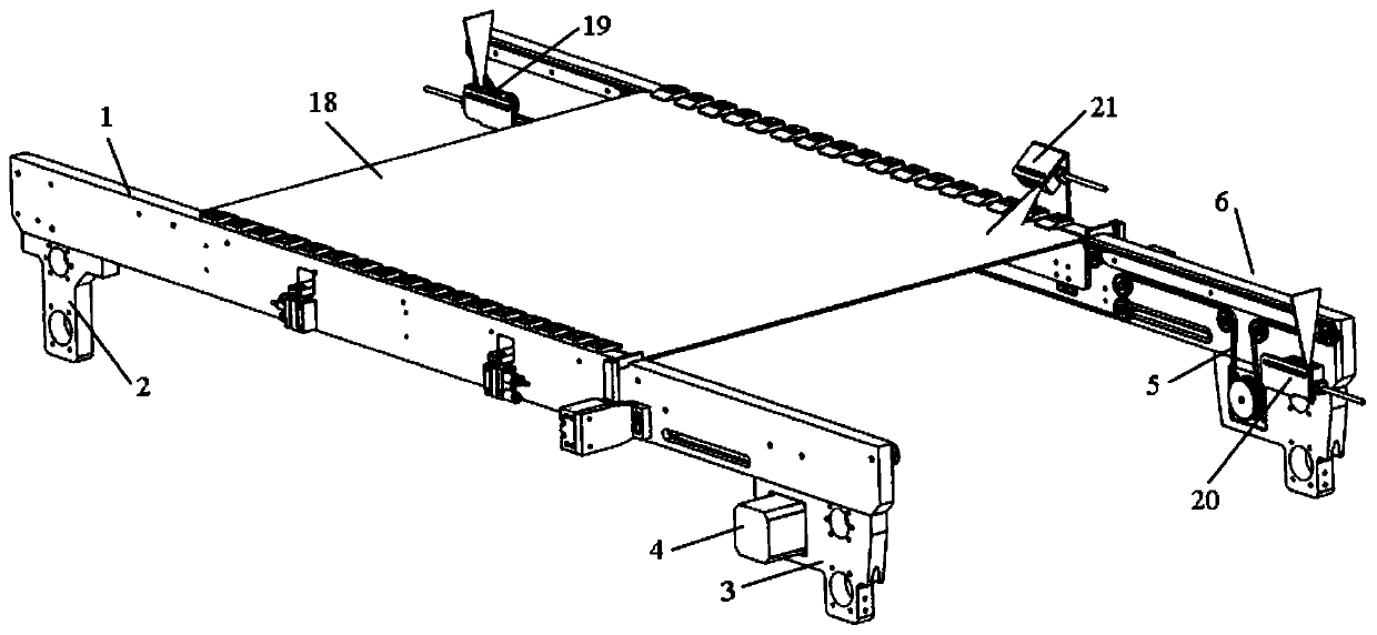
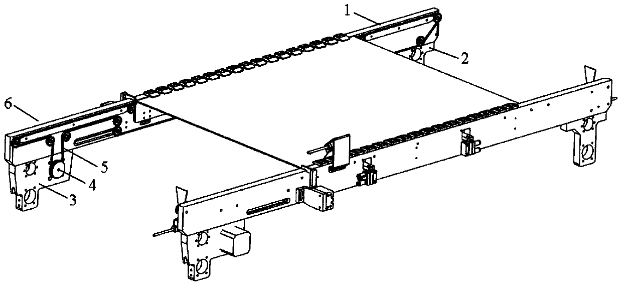
[0063] A pressing plate device includes a fixing component, a driving component and a positioning component.
[0064] as attached figure 1 and 2 As shown, the fixing assembly includes a set of support plates 1, two left supports 2 and two right supports 3, and the two ends of each support plate 1 are respectively fixed with a left support 2 and a right support 3, and the left supports 2 and 3 are respectively fixed. Support 2 and right support 3 are used for fixing this platen device on the engraving machine platform.
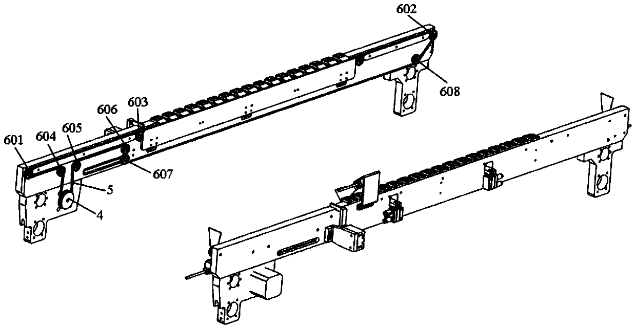
[0065] as attached image 3 As shown, the drive assembly includes a set of drive motors 4 and two belts 5, and a set of drive motors 4 are respectively fixed on the two left brackets 2 or the two right brackets 3, each of which The belt 5 is driven by a roller assembly 6 fixed on the support plate 1 .
[0066] as attached Figure 4 As shown, the roller assembly 6 includes a driving wheel 601 , a driven wheel 602 , a transition wheel and a supporting wheel ...
Embodiment 2
[0085] Based on the above-mentioned embodiment 1, the similarities will not be described in detail. The difference is that the support plate 1 is provided with a plate stop device at the output end, and the plate stop device shown is used to limit the movement of the engraving plate 18 to facilitate The positioning assembly clamps and fixes the engraving plate 18 .
[0086] as attached Figure 7 As shown, the stop board device includes a stop board support 15 , a stop board cylinder 16 and a stop board cylinder support 17 .
[0087] The stop plate cylinder 16 is fixed on the outside of the support plate 1 through the stop plate cylinder bracket 17 .
[0088] The stop plate support 15 is L-shaped, and the upper end is lapped on the passage provided at the upper end of the support plate 1, the stop plate support 15 is connected with the stop plate cylinder 16, and the stop plate cylinder 16 drives the Stop plate support 15 moves back and forth, realizes the spacing that engrav...
Embodiment 3
[0094] Based on the above-mentioned embodiments, a method for using a platen device includes the following steps:
[0095] 101. The plate-feeding monitoring device 19 senses the engraving plate 18, the drive motor 4 starts, drives the belt 5 to transmit, and drives the engraving plate 18 to transmit; at the same time, the plate-stopping device starts, and the plate-stopping cylinder 16 pushes the plate-stopping bracket 15 inward to block the plate engraving 18 continue forward transmission;
[0096] 102. The deceleration monitoring device 21 senses the engraving plate 18, and the drive motor 4 decelerates. When the engraving plate 18 reaches the position of the stop plate bracket 15, the drive motor 4 stops;
[0097] 103. After step 102, the driving cylinder 9 is started, and the top plate 8 is driven to move upward through the connecting plate 10, and a squeeze is formed between the top plate 8 and the limit block 7, and the engraving plate 18 is clamped and fixed;
[0098] ...
PUM
 Abstract
Description
Claims
Application Information
 - R&D Engineer
- R&D Manager
- IP Professional
- Industry Leading Data Capabilities
- Powerful AI technology
- Patent DNA Extraction
Browse by: Latest US Patents, China's latest patents, Technical Efficacy Thesaurus, Application Domain, Technology Topic, Popular Technical Reports.
© 2024 PatSnap. All rights reserved.Legal|Privacy policy|Modern Slavery Act Transparency Statement|Sitemap|About US| Contact US: help@patsnap.com


