
Combinable socket

A combined, socket technology, applied in the field of electricity, can solve the problems of waste of resources, difficult to select the size of the socket, etc., and achieve the effect of preventing electric shock and rusting of contact points.

Active Publication Date: 2020-03-10
安徽突飞科技股份有限公司
View PDF7 Cites 0 Cited by
  • Summary
  • Abstract
  • Description
  • Claims
  • Application Information

AI Technical Summary

Problems solved by technology

[0002] During the use of the socket, because the number of plugs that need to be inserted is uncertain, it is difficult to choose the size of the socket. If you choose a small one, there will be no place to plug in when there are many electrical appliances. When you choose too large, due to the cost and no Local placement causes a waste of resources, so a socket that can be combined at any time according to the actual situation is needed

Method used


Image

  • Combinable socket
  • Combinable socket
  • Combinable socket

Examples


specific Embodiment 1

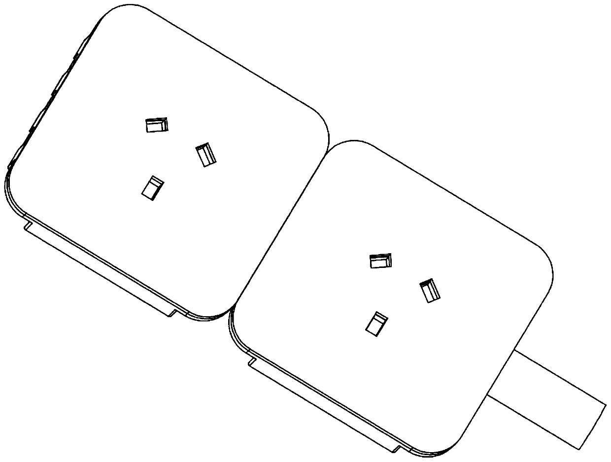
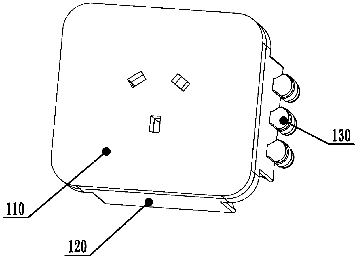
[0028] Specific embodiment one, please refer to figure 1 , figure 2 , image 3 , Figure 4 , Figure 5 , Figure 6 , Figure 7 Shown is a combinable socket, socket cover 110, socket box 120 and combined connection mechanism; it is characterized in that: the combined connection mechanism includes a protruding combination part and a concave combination part, and the combination through the protruding Parts and recessed combination parts are connected to realize the combination of multiple sockets to meet the needs of different socket numbers. Specifically, through the combination of multiple sockets, the combination of multiple sockets is realized. The contact points of the combined parts are contacted to realize electrification. The socket box 120 includes a jack portion 121 and a socket box bottom 122. The socket box bottom 122 is arranged on the socket box 120, and the jack portion 121 and the socket box bottom 122 are fixed by screws. .

[0029] Further, the combined...

specific Embodiment 2

[0034] In the second embodiment, the socket cover 110 and the socket box 120 are the same as in the first embodiment, the combined connection mechanism includes a protruding combined part B230 and a concave combined part B240; the protruding combined part B230 includes a protruding Pillar B231, the concave combination part B240 includes a combined groove B241, when combined, the protruding post B231 is inserted into the combined groove B241, specifically the shape of the protruding post B231 is the same as that of the combined groove B241, and the combined groove B241 is more convex than The post B231 is bigger, so that the protruding post B231 can be installed in the combination groove B241.

[0035] Further, the above-mentioned protruding post B231 is provided with an electric hole, and a contact post 242 is provided in the combined groove B241. When assembling, the circuit is connected by inserting the contact post 242 into the electric hole above the protruding post B231 ,...


PUM


Abstract

A combinable socket comprises a socket cover plate, a socket box and a combined connecting mechanism. The combinable socket is characterized in that the combined connecting mechanism includes a convexcombined portion and a concave combined portion; the convex combined portion and the concave combined portion are connected to realize combination of a plurality of sockets so as to satisfy requirements of different numbers of sockets; furthermore, the combined connecting mechanism includes a convex combined portion A and a concave combined portion A, and the convex combined portion A includes aconvex column A; the concave combination portion A includes a combination groove A; and during combination, the convex column A is inserted into the combination groove A. By using the combinable socket, the two sockets are connected through the combination of the convex combined portion and the concave combined portion and the connection of the plurality of sockets is realized, and demands of thedifferent numbers of sockets are satisfied. Sealing is completed through arrangement of a sealing semi-circular ring A, a sealing column and a sealing plate B, and electric shock and rusting of contact points in a using process are prevented.

Description

technical field [0001] The invention relates to the technical field of electric power, in particular to a combinable socket. Background technique [0002] During the use of the socket, because the number of plugs that need to be inserted is uncertain, it is difficult to choose the size of the socket. If you choose a small one, there will be no place to plug in when there are many electrical appliances. When you choose too large, due to the cost and no Local placement causes a waste of resources, so a socket that can be combined at any time according to the actual situation is needed. Contents of the invention [0003] Aiming at the above problems, the present invention provides a combinable socket. The two sockets are connected through the combination of the protruding combination part and the concave combination part, which realizes the connection of multiple sockets and satisfies the requirements of different numbers of sockets. Requirements: The sealing is completed by...

Claims


Application Information

Patent Timeline
Patent Type & Authority Applications(China)
IPC IPC(8): H01R13/10H01R13/514H01R13/52
CPCH01R13/10H01R13/514H01R13/52H01R13/5202H01R13/5219
Inventor 郭佳伟
Owner 安徽突飞科技股份有限公司
Learn More