
Liquid pump and motor vehicle with a liquid pump

A technology for motor vehicles and liquid pumps, applied in liquid fuel engines, parts of pumping devices for elastic fluids, machines/engines, etc., can solve problems such as increased wear and tear, and achieve the effect of reducing mechanical wear, compactness and maintenance-free

Pending Publication Date: 2020-03-10
FORD GLOBAL TECH LLC
View PDF8 Cites 0 Cited by
  • Summary
  • Abstract
  • Description
  • Claims
  • Application Information

AI Technical Summary

Problems solved by technology

[0010] Typically, rotating bodies vibrate or oscillate, for example due to unbalanced rotating masses, which can lead to increased wear, generation of structure-borne and / or air-borne noise, etc.

Method used


Image

  • Liquid pump and motor vehicle with a liquid pump

Examples


Embodiment Construction

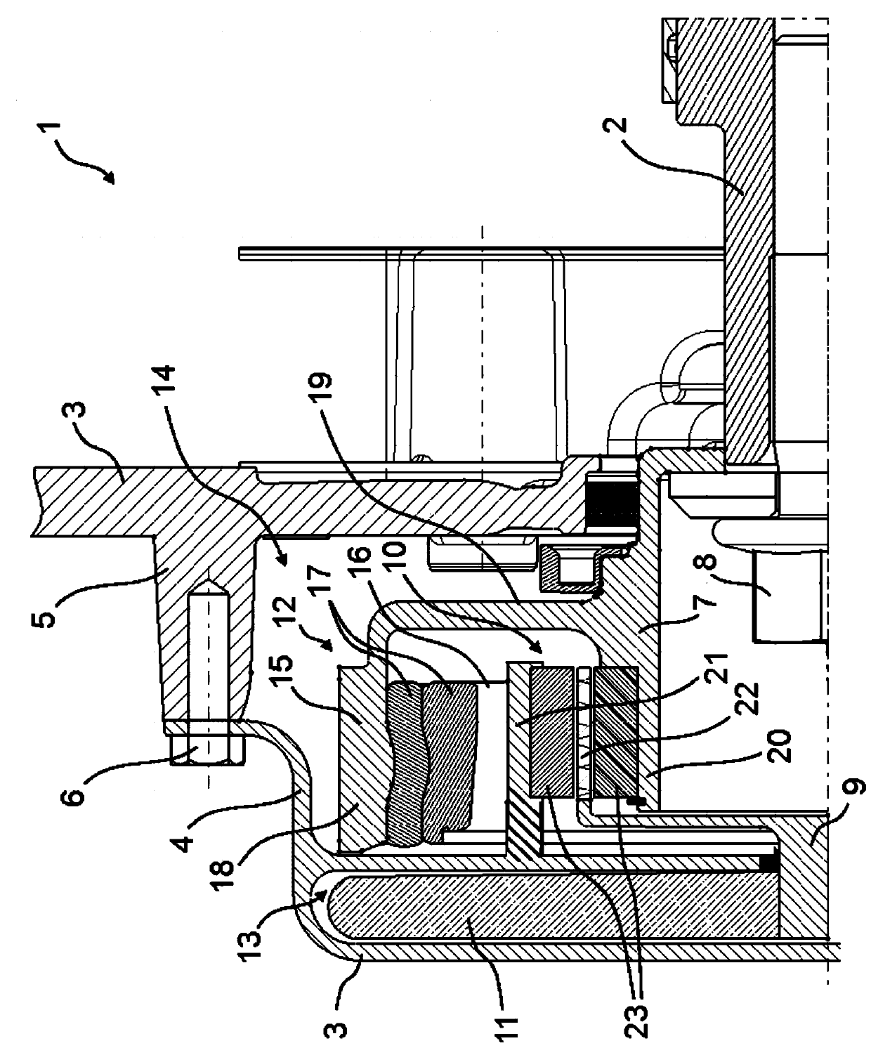
[0031] figure 1 A partial longitudinal section (in the present case upper half) of an exemplary embodiment of a liquid pump 1 for a motor vehicle according to the invention is shown schematically, not shown in detail. In the case of the illustrated exemplary embodiment, the liquid pump 1 is a water pump, and the motor vehicle including the liquid pump 1 is a hybrid vehicle. In addition to an electric motor, not shown, the hybrid vehicle also has an internal combustion engine (not shown), which drives the crankshaft 2 . from figure 1 As can be clearly seen in , the crankshaft 2 of the internal combustion engine is directly and rigidly connected to the pump 1 in order to drive it, as will be explained in more detail below.

[0032] from figure 1 It can also be seen in the figure that the pump 1 has a two-part housing 3 which in turn has a detachable cover 4 which can be removed, for example via figure 1 The screw arrangement 6 visible in is fastened to the housing plate 5 . ...


PUM


Abstract

The invention relates to a liquid pump and a motor vehicle with a liquid pump. The invention relates to a liquid pump (1) for transporting liquids for motor vehicles, which has a housing (3), a driveshaft (7) at least partially rotatably supported in the housing (3), an output shaft (9) which is rotatably supported in the housing (3) and connected to the drive shaft (7) in a non-contact manner via a torque transmission effect via a magnetic transmission device (10), and a pump impeller (11) which is connected to the output shaft (9) in a torsionally rigid manner. The mass spring damper unit (12) contained in the housing (3) is connected to the drive shaft (7) in a torsionally rigid manner so as to rotate together with the same. The mass spring damper unit (12) is designed and arranged todamp the vibration of the drive shaft (7) in the radial and / or axial and / or tangential directions. The invention further relates to a motor vehicle, in particular a hybrid vehicle, with an internal combustion engine and a crankshaft (2), wherein the crankshaft (2) is driven by the internal combustion engine and is rigidly connected to the drive shaft (7) of this liquid pump (1).

Description

technical field [0001] The invention relates to a liquid pump for a motor vehicle according to the preamble of claim 1 . The invention also relates to a motor vehicle with a liquid pump according to the preamble of claim 9 . Background technique [0002] Motor vehicles having a liquid pump, such as a coolant pump for conveying coolant through a cooling circuit of an internal combustion engine and / or an electric machine, and liquid pumps of this type are known in various embodiments. [0003] Thus, for example, US 6 007 303 A (ie DE 197 46 359 A1) discloses a controllable coolant pump for a motor vehicle, the drive shaft of which is driven by the internal combustion engine of the motor vehicle via a belt drive. A pump impeller arranged on the output side of the pump is connected to the drive shaft via a magnetic clutch with a torque-transmitting effect, wherein the magnetic clutch has two clutch disks which are spaced apart in the axial direction via an air gap. The first c...

Claims


Application Information

Patent Timeline
IPC IPC(8): F04D13/02F04D29/66
CPCF04D13/024F04D29/669F01P5/12F01P7/162
Inventor R·基恩G·卢旺K·狄龙C·尼德胡特M·K·施普林格
Owner FORD GLOBAL TECH LLC
Learn More