Wheel hub, system consisting of a brake disc and a wheel hub, and method for mounting a brake disc on a wheel hub

A technology of brake discs and hubs, applied in the directions of brake discs, brake components, hubs, etc., can solve problems such as the inability to achieve braking torque

Active Publication Date: 2020-03-06
SAF HOLLAND GMBH
View PDF5 Cites 0 Cited by
  • Summary
  • Abstract
  • Description
  • Claims
  • Application Information

AI Technical Summary

Problems solved by technology

Furthermore, no further increase in braking torque can be achieved

Method used


Image

  • Wheel hub, system consisting of a brake disc and a wheel hub, and method for mounting a brake disc on a wheel hub
  • Wheel hub, system consisting of a brake disc and a wheel hub, and method for mounting a brake disc on a wheel hub
  • Wheel hub, system consisting of a brake disc and a wheel hub, and method for mounting a brake disc on a wheel hub

Examples


Embodiment Construction

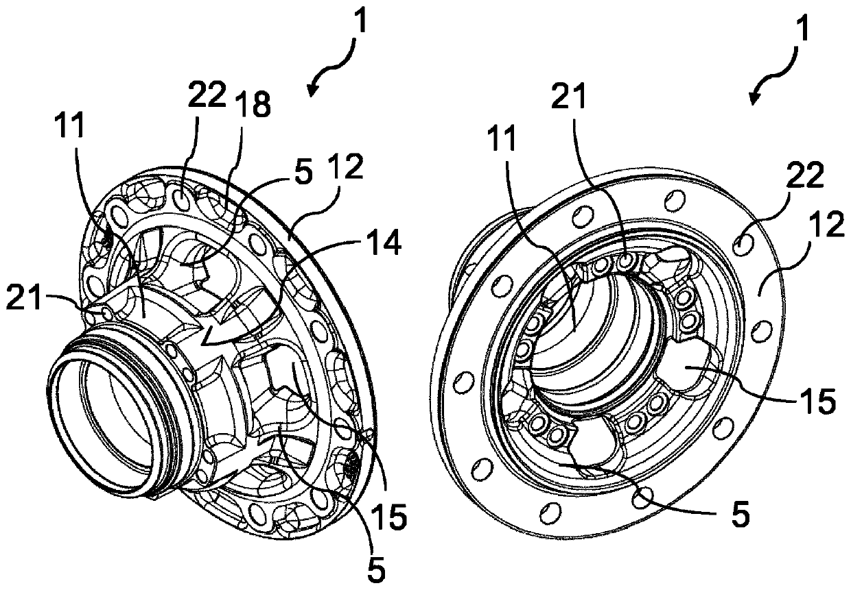
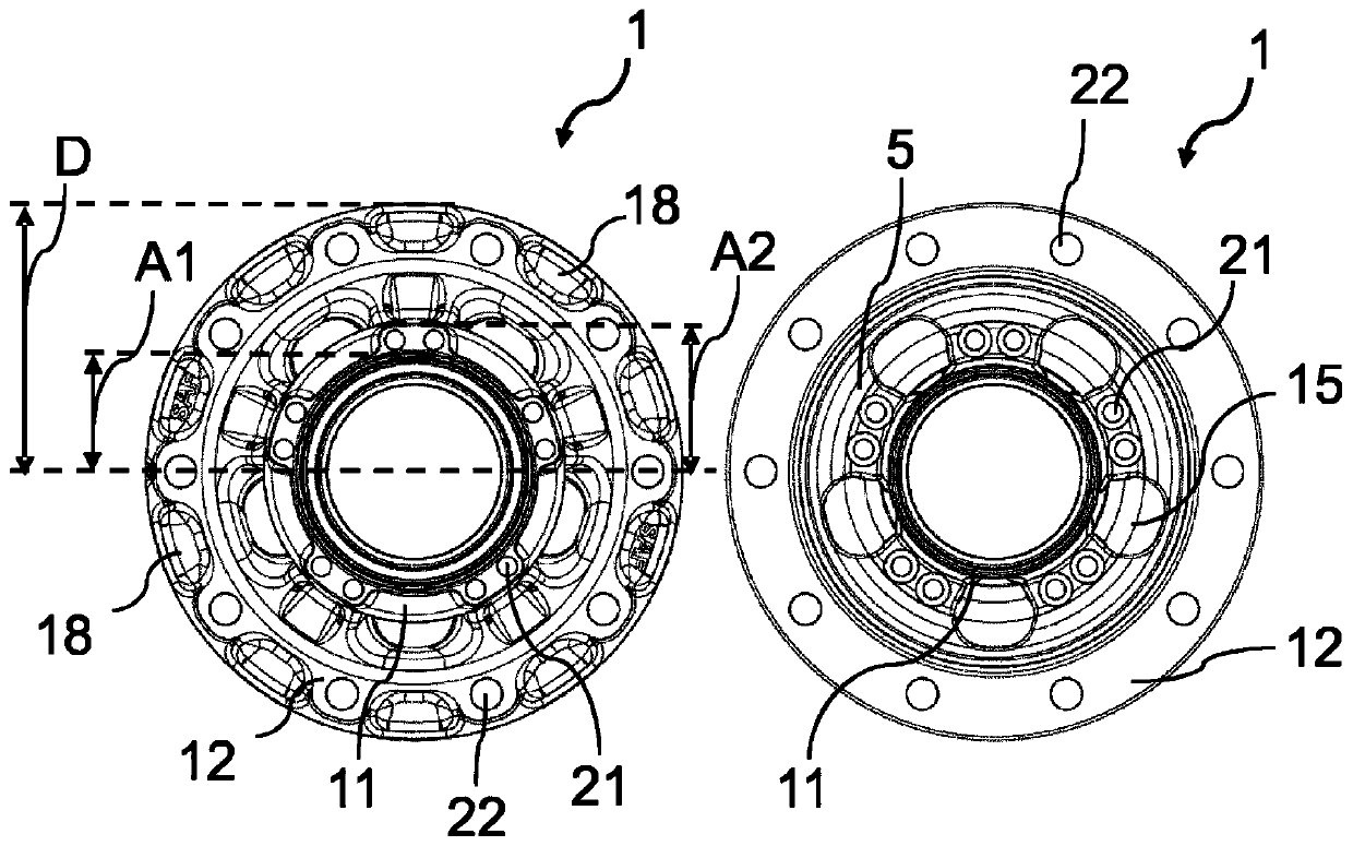
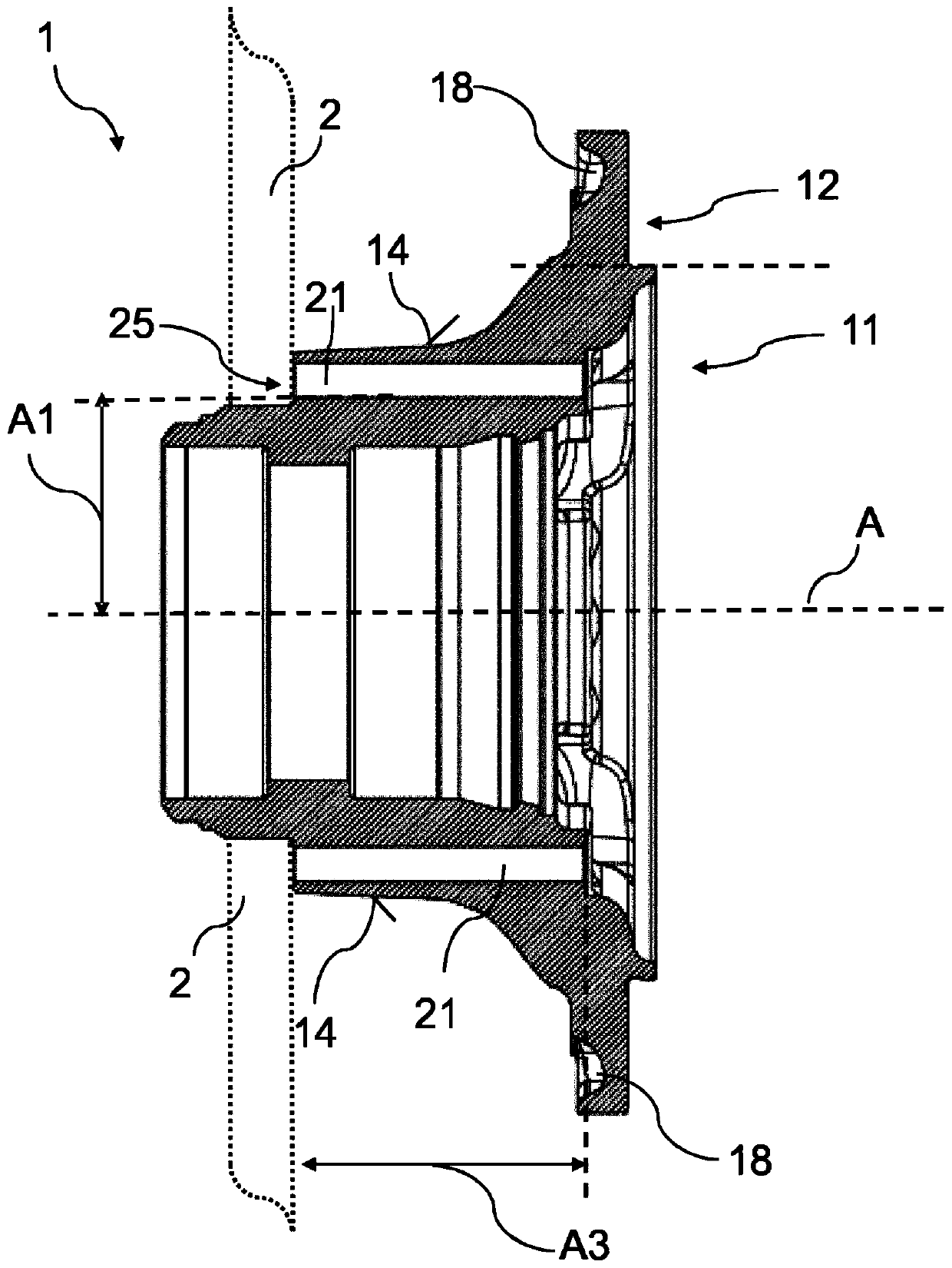
[0034] Figures 1a to 1c A hub 1 according to a first exemplary embodiment of the invention is shown. Figure 1a Two perspective views are shown, Figure 1b is a top view of the rear side (left side) and front side (right side) of the hub 1, and Figure 1c is a sectional view. Such a hub 1 is used to fasten a wheel to an axle element, for example to an axle stub, an axle rod or an axle. In addition to the connection to the wheel, the brake disc 2 is also connected to the hub 1 for rotation therewith. Preferably, this is a hub 2 for a commercial vehicle (Nutzfahrzeug / utility vehicle). In particular, the hub 1 is formed in a single piece or in an integrated form. That is to say, on the monolithic hub 1 , there is not only a first notch 21 for connecting the brake disc 2 to the hub 1 , but also a second notch 22 for connecting the wheel to the hub 1 . The main parts of the integrally constructed hub 1 are the outer collar region 12 when viewed in the radial direction and the...


PUM


Abstract

The invention relates to a wheel hub (1) comprising a radially outer collar region (12) and a radially inner core region (11), the inner core region (11) being thicker in the axial direction than theouter collar region (12), and the wheel hub (11) having, in the inner core region (11), a substantially axial primary cut-out (21) for attaching a brake disc.

Description

technical field [0001] The invention relates to a hub, a system consisting of a brake disc and a hub and a method for installing a brake disc on the hub. Background technique [0002] Wheel hubs are well known in the art. They are used to connect wheels to axle elements, for example to the axles of commercial vehicles. Here, the brake disc is usually connected to the hub for rotation therewith. The brake disc is usually threaded to the hub from the disc side. Therefore, the clamping length (ie, the total thickness formed in the connection direction between the connected element and the fastener for the connection) is mounted by the substantially planar brake element or adapter element and the setback on the vehicle. The construction space of the visible side of the hub is limited. Therefore, fasteners such as screws must have a correspondingly high strength to apply the required support force. Furthermore, no further increase in braking torque can be achieved. Content...

Claims


Application Information

Patent Timeline
Patent Type & Authority Applications(China)
IPC IPC(8): F16D65/12B60B27/00
CPCB60B27/0052F16D65/123F16D2065/1356F16D2065/1384B60B27/02B60B2320/10B60B2900/111B60B2900/3312B60B2900/513
Inventor 弗雷德里克·比尔约纳斯·马特恩穆罕默德·阿尔帕斯彼得·图卡克斯特凡·瓦迈耶
Owner SAF HOLLAND GMBH
Why Eureka
Try Eureka